
Comprehensive Guide to a 4-Way Traffic Light System with IR Sensors and Pedestrian Control
Implementing an Intelligent Traffic Management Solution Using Arduino
Key Highlights of the Project
- Sensor-Based Traffic Density Detection: Utilizing four IR sensors, one for each approach, to dynamically assess traffic volume and optimize signal timing.
- Pedestrian Priority Integration: Implementing a pedestrian request system that interrupts the normal traffic cycle to allow safe crossing when a button is pressed.
- Arduino Control System: Employing an Arduino microcontroller to manage the logic and sequencing of the traffic lights and pedestrian signals.
Introduction to Intelligent Traffic Control
Modern traffic management systems aim to optimize traffic flow and enhance safety for both vehicles and pedestrians. Traditional time-based traffic lights follow a fixed sequence, which can lead to unnecessary delays during periods of low traffic. By incorporating sensors, traffic lights can become more dynamic and responsive to real-time conditions. This project focuses on building a 4-way traffic light control system that uses IR sensors to detect vehicle presence and a pedestrian button for requested crossings, all managed by an Arduino microcontroller.
This intelligent approach allows the system to adjust signal timings based on actual traffic density, potentially reducing congestion and improving overall efficiency. Furthermore, the inclusion of pedestrian control ensures that individuals can safely cross the intersection when needed, providing a dedicated phase for them.
Understanding the Components
To build this 4-way traffic light system with IR sensors and pedestrian control, several key components are required. Each component plays a vital role in the system's functionality.
Arduino Microcontroller
The Arduino board serves as the brain of the operation. It processes the input from the IR sensors and the pedestrian button and controls the state of the traffic lights and pedestrian signals. An Arduino UNO is a common choice for such projects due to its versatility and ease of use.
An Arduino board connected to traffic light components.
IR Sensors
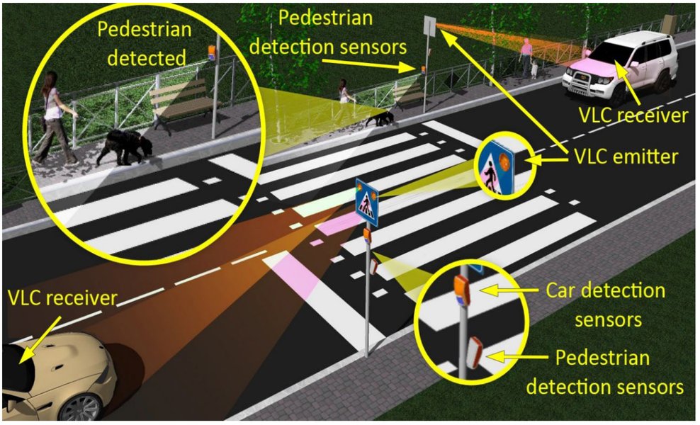
Infrared (IR) sensors are used to detect the presence of vehicles approaching the intersection. One sensor is typically placed on each of the four roads leading to the intersection. When a vehicle breaks the infrared beam, the sensor sends a signal to the Arduino, indicating traffic is present on that approach.
Infrared sensors can be utilized for traffic detection.
Traffic Lights (LEDs)
Each of the four approaches will have a set of traffic lights, typically consisting of red, yellow, and green LEDs. These LEDs are connected to the digital output pins of the Arduino and are illuminated in sequence to control traffic flow.
Pedestrian Signals (LEDs)
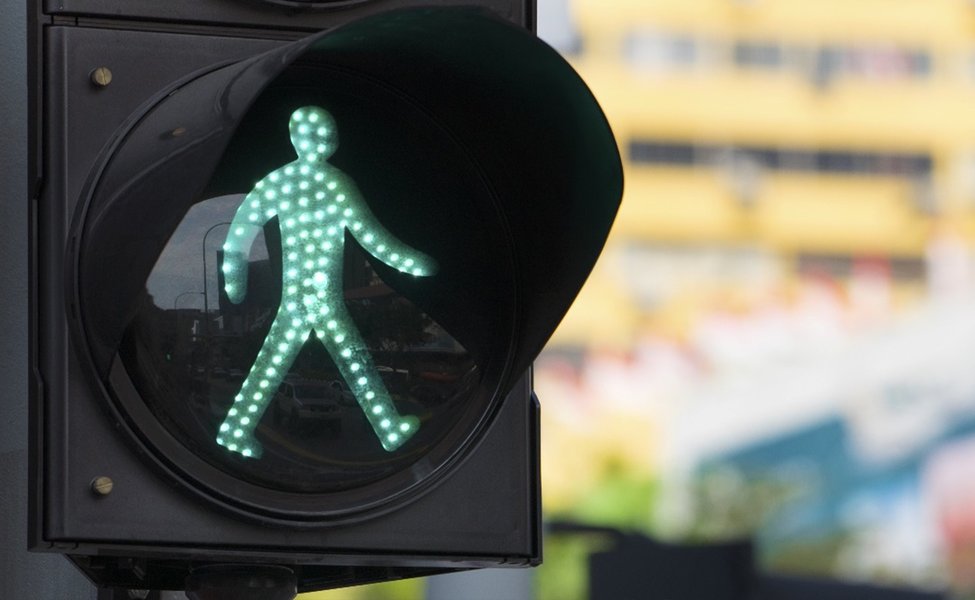
For pedestrian crossings, dedicated pedestrian signals are needed. These usually consist of two LEDs: one indicating "walk" (often a green or white walking figure) and one indicating "don't walk" (often a red or orange hand). These are also connected to the Arduino's output pins.
A typical pedestrian crossing signal with "walk" and "don't walk" indicators.
Pedestrian Push Button
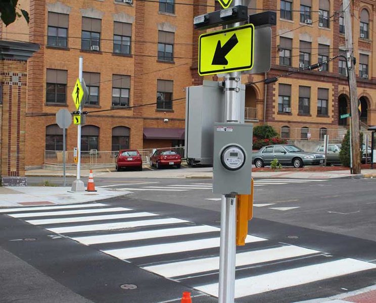
A push button is placed at the pedestrian crossing to allow pedestrians to request a signal change. When the button is pressed, it sends a signal to the Arduino, initiating the pedestrian crossing sequence.
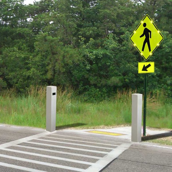
Pedestrian push button for requesting a crossing.
Circuit Design and Wiring
Connecting all the components correctly is crucial for the system to function as intended. The Arduino pins will be used for both input (from sensors and button) and output (to control LEDs).
Wiring the Traffic Lights
Each traffic light set (red, yellow, green) for the four ways will be connected to separate digital output pins on the Arduino. Resistors should be used in series with each LED to limit the current and prevent them from burning out. The negative terminals of all LEDs should be connected to the ground pin of the Arduino.
Wiring the IR Sensors
The four IR sensors will be connected to digital input pins on the Arduino. The sensors typically have VCC, GND, and an output pin. VCC and GND are connected to the Arduino's power and ground, and the output pin is connected to a digital input pin.
Wiring the Pedestrian Button
The pedestrian push button is connected to a digital input pin on the Arduino. A pull-down or pull-up resistor is usually required to ensure a stable input signal when the button is not pressed.
Example Wiring Diagram Considerations
While a specific diagram will depend on the chosen Arduino board and components, the general principle involves connecting the outputs of the sensors and button to Arduino input pins and the inputs of the LEDs to Arduino output pins. Proper grounding is essential for all components.
Arduino Code Structure and Logic
The Arduino code will implement the logic for the traffic light sequencing, sensor processing, and pedestrian control. The code will need to manage the states of the traffic lights and pedestrian signals based on the inputs received.
Defining Pin Assignments
The first step in the code is to define which Arduino pins are connected to which component (LEDs, sensors, button). This makes the code more readable and easier to modify.
// Define pin numbers for traffic lights (e.g., for one way)
const int carRed1 = 9;
const int carYellow1 = 8;
const int carGreen1 = 7;

// Define pin numbers for IR sensors
const int irSensor1 = 2;
// ... define for other sensors

// Define pin numbers for pedestrian signal
const int pedRed = 11;
const int pedGreen = 10;

// Define pin number for pedestrian button
const int pedButton = 12;
Implementing the Traffic Light Sequence
The core of the code will be the logic that controls the traffic light sequence for the four ways. This can be implemented using state machines or a series of timed delays. The sequence should typically follow the standard red, red-yellow, green, yellow, red pattern for each approach while coordinating with the other approaches.
Reading Sensor Inputs
The Arduino will constantly read the state of the IR sensors to detect vehicle presence. If a sensor detects a vehicle, this information can be used to influence the traffic light timing, potentially giving more time to approaches with higher traffic density.
Handling Pedestrian Requests
The code needs to monitor the state of the pedestrian button. When the button is pressed, the system should initiate a sequence that brings the vehicular traffic lights to red on the relevant approaches and activates the pedestrian "walk" signal. This sequence should include appropriate safety delays.
Integrating Sensor and Pedestrian Logic
The most complex part is combining the sensor data and pedestrian requests with the standard traffic light sequence. The system needs to prioritize pedestrian requests when made, but also manage the vehicular traffic flow based on sensor input when no pedestrian request is active.
An Arduino-based traffic light system with pedestrian crossing.
Code Snippet for Pedestrian Control Logic
Here's a simplified example of how you might implement the logic for a pedestrian request when the button is pressed, assuming the traffic lights are currently green for one direction:
void loop() {
  // ... normal traffic light sequencing ...

  if (digitalRead(pedButton) == HIGH) { // Check if pedestrian button is pressed
    // Assuming carGreen1 is currently HIGH
    digitalWrite(carGreen1, LOW); // Turn off green
    digitalWrite(carYellow1, HIGH); // Turn on yellow
    delay(3000); // Yellow light duration
    digitalWrite(carYellow1, LOW); // Turn off yellow
    digitalWrite(carRed1, HIGH); // Turn on red

    // Wait for all car lights to be red before pedestrian walk
    // (This part would need to be more sophisticated for a 4-way intersection)
    delay(1000); // Short delay

    digitalWrite(pedRed, LOW); // Turn off pedestrian don't walk
    digitalWrite(pedGreen, HIGH); // Turn on pedestrian walk
    delay(5000); // Pedestrian crossing time
    digitalWrite(pedGreen, LOW); // Turn off pedestrian walk
    digitalWrite(pedRed, HIGH); // Turn on pedestrian don't walk

    // Resume normal traffic sequence
  }
}
This is a very basic example and a full implementation for a 4-way intersection with sensors would require more complex state management and timing logic.
Advanced Considerations and Enhancements
Once the basic system is functional, several enhancements can be considered to make the traffic control more sophisticated and efficient.
Traffic Density Measurement
Instead of just detecting the presence of a single vehicle, the system could potentially measure traffic density by counting the number of times the IR sensor is triggered within a certain period or by using more advanced sensors. This data could then be used to dynamically adjust the green light duration for each approach.
Optimizing Signal Timing
Based on traffic density data, algorithms can be implemented to optimize the timing of the traffic lights. This could involve techniques like adaptive signal control, where the green light duration is extended for approaches with heavy traffic and shortened for those with less traffic.
Implementing a State Machine
For more complex control logic, especially with multiple states and transitions (like a 4-way intersection with pedestrian control), implementing a finite state machine in the code can make the program more organized and easier to debug.
A representation of a state machine which can be used for traffic light control.
Adding an Emergency Vehicle Override
For emergency vehicles, a system could be implemented to allow them to override the normal traffic sequence and immediately get a green light on their approach.
Wireless Communication
For larger or more distributed systems, wireless communication modules (like NRF24L01) could be used to allow different parts of the system to communicate with each other, for example, to coordinate multiple intersections.
Comparison of Traffic Light Control Methods
Here's a table comparing different methods for controlling traffic lights:
| Control Method | Description | Advantages | Disadvantages | Complexity |
|---|---|---|---|---|
| Time-Based | Fixed timing for each light phase. | Simple to implement, predictable. | Inefficient with varying traffic, doesn't react to real-time conditions. | Low |
| Sensor-Based (Presence) | Uses sensors (like IR) to detect if vehicles are present. | More responsive than time-based, can skip phases if no traffic. | Doesn't measure density, limited optimization. | Medium |
| Density-Based | Uses sensors to estimate traffic volume. | Optimizes green light duration based on traffic, reduces waiting times. | Requires more complex sensors and algorithms. | High |
| Pedestrian Activated | Includes a button for pedestrians to request a crossing. | Provides safe crossing for pedestrians on demand. | Can interrupt vehicular flow, timing needs careful consideration. | Medium to High |
| Adaptive Control | Uses real-time data (sensors, cameras) to dynamically adjust timing across multiple intersections. | Significantly optimizes traffic flow, reduces congestion. | Very complex system and infrastructure required. | Very High |
Implementing Pedestrian Priority Clearly
Implementing pedestrian priority in a 4-way system requires careful sequencing to ensure safety. When a pedestrian button is pressed, the system should:
- Complete the current green light phase for the active vehicular traffic.
- Transition the relevant vehicular lights through yellow to red. This must be done for all approaches that could conflict with the pedestrian crossing.
- Activate the pedestrian "walk" signal for a sufficient duration.
- After the pedestrian "walk" time, transition to the pedestrian "don't walk" signal.
- Ensure a brief clearance interval before the vehicular lights change from red to green again.
The timing for each of these steps is crucial and should be set to allow enough time for vehicles to stop and pedestrians to cross safely.
Troubleshooting Common Issues
When building this project, you might encounter some common issues:
- Incorrect Wiring: Double-check all connections, ensuring LEDs are connected with the correct polarity and resistors are in place.
- Code Errors: Syntax errors, logical errors in the sequencing, or issues with reading sensor/button inputs are common. Use the Arduino IDE's serial monitor to debug.
- Sensor Sensitivity: IR sensor sensitivity might need adjustment depending on the environment and the expected range of detection.
- Timing Issues: If traffic flow is not smooth or pedestrian crossing time is insufficient, adjust the delay values in the code.
FAQ
Frequently Asked Questions
What type of IR sensor is best for this project?
Basic IR obstacle avoidance sensors are generally suitable for detecting the presence of a vehicle. Ensure they have adjustable sensitivity if needed.
How long should the pedestrian crossing time be?
The pedestrian crossing time should be long enough for a person to safely cross the width of the road. This will vary depending on the specific intersection. A common guideline is to allow about 1 meter per second, plus an initial startup interval.
Can I use different types of sensors?
Yes, other types of sensors like ultrasonic sensors or pressure sensors could also be used for vehicle detection, although IR sensors are often simpler for basic presence detection.
How can I make the traffic light timing more realistic?
To make the timing more realistic, you would need to implement more sophisticated logic that considers factors like minimum green times, clearance intervals, and possibly even preemption for emergency vehicles.
Recommended Queries
- arduino traffic light code with pedestrian button
- density based traffic light control arduino ir sensor
- finite state machine traffic light controller
- interfacing ir sensor with arduino
References
Last updated May 18, 2025