
Comprehensive Guide to Arduino-Based Height Detector
Designing and implementing a circuit to block over-height vehicles
Key Insights
- Reliable Sensing: Use an infrared transmitter and receiver pair to detect blockages.
- Clear Indication: Switch LED indicators and LCD messages to warn when a vehicle exceeds height limits.
- Robust Wiring and Code: Integrate sensors, LEDs, LCD, and optionally a buzzer with an Arduino using optimized wiring and sample code.
Overview
This guide explains how to build and implement an Arduino-based height detection system at a tunnel entrance. The system detects over-height vehicles by monitoring an infrared (IR) beam. When a vehicle blocks the IR beam, a red LED illuminates and the LCD display shows the word “STOP” to prevent safety hazards. In the absence of blockage, the green LED remains active and the display indicates a clear path. This project involves careful planning of both the electronic circuit and the software logic using the Arduino IDE. Detailed wiring instructions, a circuit diagram, and annotated code examples are provided to help you successfully build the system.
Components and Circuit Setup
Components Required
Before starting, ensure you have all the necessary parts:
- Arduino Uno board (or a compatible Arduino model)
- Infrared (IR) transmitter and receiver pair
- Green and Red LED lights
- 16×2 LCD display (I2C or parallel interface)
- Resistors (Typically 220Ω for the LED circuits; additional resistor types may be required for sensor interfacing)
- Jumper wires and breadboard
- Optional: Piezo buzzer for auditory warnings
- Power supply (USB cable or 9V battery for standalone operation)
Wiring Diagram and Instructions
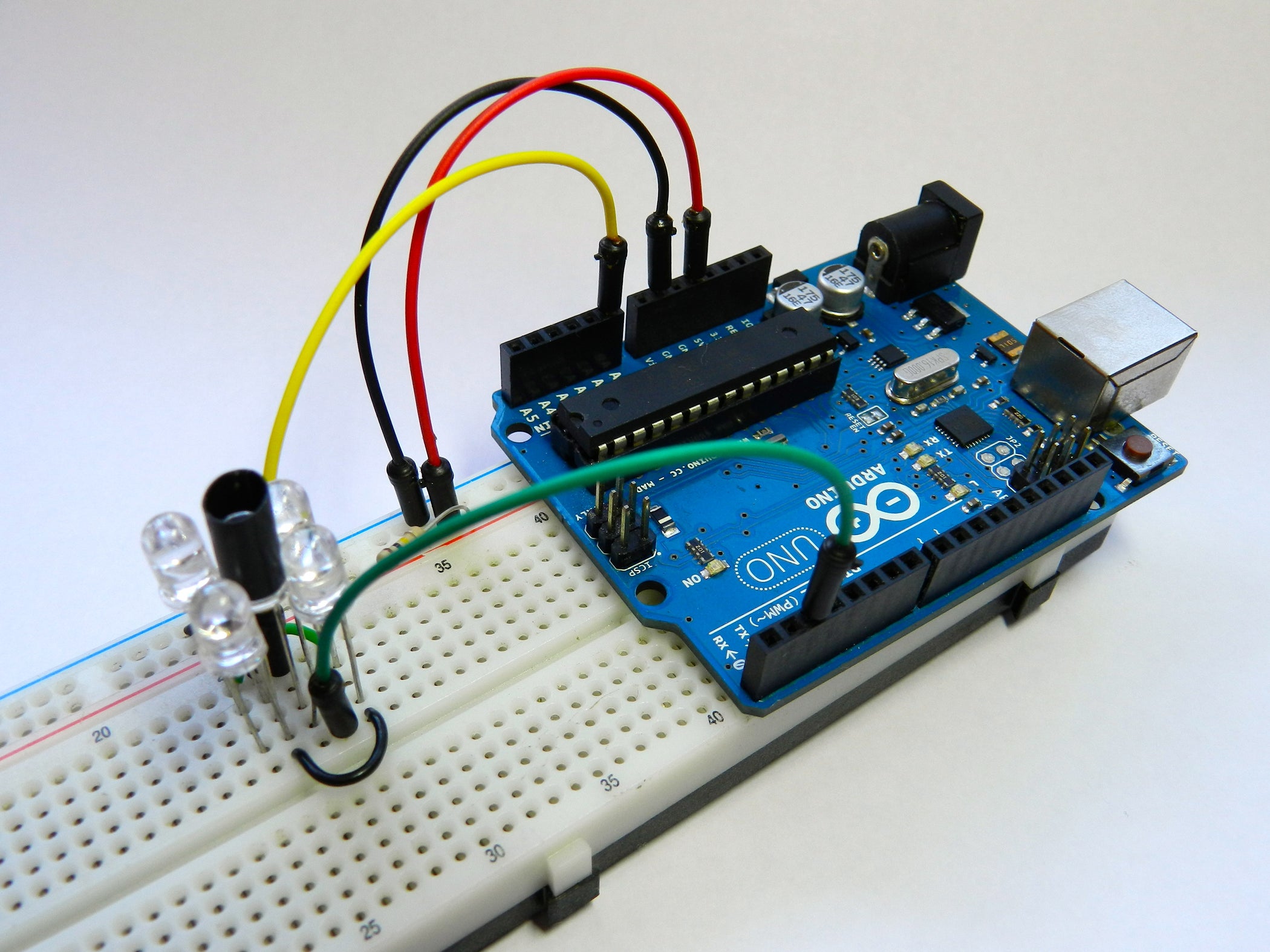
The circuit involves connecting the IR sensor, LEDs, and LCD display to the Arduino. Below is a detailed wiring guide along with a simplified diagram. Although a photo is recommended for clarity, the diagram below serves as a reference to help you correctly connect the components.
Infrared Sensor Wiring
Connections:
- IR Transmitter: Connect the VCC pin to the Arduino’s 5V output and ground to GND. Position the transmitter so it projects the IR beam across the tunnel entrance.
- IR Receiver: Connect its VCC to 5V, GND to GND, and the output signal to one of the digital input pins on the Arduino (for example, pin 2).
LED Wiring
Connections:
- Green LED: Connect the anode (longer leg) to a digital output pin (for instance, pin 8) through a 220Ω resistor, and connect the cathode to the Arduino’s ground (GND).
- Red LED: Connect the anode to another digital output pin (for example, pin 9) through a 220Ω resistor, with the cathode connected to GND.
LCD Display Wiring
There are two common ways to connect an LCD display:
- I2C Interface: Connect the LCD’s VCC to the 5V on Arduino and GND to ground, then SDA (data line) to the Arduino’s SDA (typically A4) and SCL to the SCL (typically A5).
- Direct (Parallel) Interface: Connect the LCD pin-by-pin (RS, EN, D4, D5, D6, D7) to the selected digital pins on the Arduino as per your project’s requirements. For this guide, we will refer to an I2C connection method because of ease and reduced wiring.
Optional: Piezo Buzzer Wiring
If you wish to provide an auditory warning:
- Connect the positive (long lead) of the piezo buzzer to a digital output pin (e.g., pin 10) via a resistor if needed, and connect the negative (short leg) to GND on the Arduino.
The universal wiring layout is summarized in the table below:
| Component | Connection | Arduino Pin / Note |
|---|---|---|
| IR Transmitter | VCC to 5V, GND to GND | Positioned to send IR beam |
| IR Receiver | VCC to 5V, GND to GND, OUT to digital input | Digital Pin 2 (example) |
| Green LED | Anode to digital output via 220Ω, Cathode to GND | Digital Pin 8 (example) |
| Red LED | Anode to digital output via 220Ω, Cathode to GND | Digital Pin 9 (example) |
| LCD Display (I2C) | VCC→5V, GND→GND, SDA→A4, SCL→A5 | I2C Address typically 0x27 |
| Piezo Buzzer (Optional) | Positive lead to digital output, Negative lead to GND | Digital Pin 10 (example) |
Arduino Code Explanation
The following Arduino sketch is designed to implement the height detection behavior. The code checks the IR receiver’s output to determine whether the IR beam is blocked by an over-height vehicle. If the beam is interrupted, the code turns on the red LED and the LCD displays "STOP". Otherwise, it keeps the green LED on and displays a safe message on the LCD.
Complete Arduino Sketch
// Include necessary libraries for LCD (I2C)
#include <LiquidCrystal_I2C.h>
#include <Wire.h>

// Define LCD (adjust I2C address if needed)
LiquidCrystal_I2C lcd(0x27, 16, 2);

// Define pin assignments
const int irReceiverPin = 2;      // IR Receiver signal pin
const int greenLedPin   = 8;      // Green LED pin
const int redLedPin     = 9;      // Red LED pin
const int buzzerPin     = 10;     // Optional: Piezo buzzer pin

void setup() {
  // Initialize serial communication for debugging (optional)
  Serial.begin(9600);

  // Initialize LCD
  lcd.init();
  lcd.backlight();
  lcd.print("System Booting...");

  // Set pin modes
  pinMode(irReceiverPin, INPUT);
  pinMode(greenLedPin, OUTPUT);
  pinMode(redLedPin, OUTPUT);
  pinMode(buzzerPin, OUTPUT); // For audio warnings (optional)

  // Initialize LED state (green on, red off)
  digitalWrite(greenLedPin, HIGH);
  digitalWrite(redLedPin, LOW);
  noTone(buzzerPin); // Ensure buzzer is off

  delay(2000);  // Wait for 2 seconds for initialization
  // Show system ready message
  lcd.clear();
  lcd.print("System Ready");
  delay(1000);
}

void loop() {
  // Read the state of the IR receiver
  int irState = digitalRead(irReceiverPin);

  // Debug output (optional)
  Serial.print("IR State: ");
  Serial.println(irState);

  // If the IR beam is blocked (assuming LOW means blockage detected)
  if (irState == LOW) {
    // Indicate detection with LED and LCD
    digitalWrite(greenLedPin, LOW);
    digitalWrite(redLedPin, HIGH);
    lcd.clear();
    lcd.print("STOP");
    // Optional: Activate audible warning
    tone(buzzerPin, 1000);  // Emit tone at 1000 Hz
  } else {
    // No blockage - safe to proceed
    digitalWrite(redLedPin, LOW);
    digitalWrite(greenLedPin, HIGH);
    lcd.clear();
    lcd.print("All Clear");
    noTone(buzzerPin);     // Stop the buzzer sound if active
  }

  delay(100);  // Delay for stability (100 ms)
}
Code Walkthrough
Library Inclusion
The program starts by including the necessary libraries: LiquidCrystal_I2C for handling the LCD, and Wire for I2C communication. This ensures that the LCD can easily be connected and controlled using just two data lines (SDA and SCL).
Pin Configuration
Each component is assigned a digital pin. The IR receiver’s output is on digital pin 2. Two digital pins are dedicated for LED output – one for the green LED and one for the red LED. An additional pin is optionally used for a piezo buzzer to generate an audible warning when the beam is blocked.
Setup Routine
The setup() function initializes the LCD and sets the correct pin modes (input for the IR receiver, output for LEDs and buzzer). The green LED is switched on to indicate that the path is clear, while the red LED remains off. A short delay allows the system to display an initial boot message before transitioning into a ready state.
Loop Function
The loop() function continuously monitors the IR receiver. When the IR beam is interrupted (detected by a LOW state), the system responds by turning off the green LED and activating the red LED. The LCD then displays the word “STOP”, and if you have connected a buzzer, it issues a tone at 1000 Hz to alert nearby personnel. If the beam is uninterrupted, the system resets to a “clear” state by displaying "All Clear" on the LCD and reactivating the green LED.
Visualizing Your Circuit with a Schematic
While photos of the actual build can be extremely helpful, you can also refer to the following schematic diagram to visualize the circuit connections:

This schematic includes:
- An Arduino board with all components connected as detailed above.
- The IR transmitter and receiver placed at opposite sides of the tunnel entrance.
- The green and red LEDs with appropriate resistors.
- The I2C LCD display, wired with SDA and SCL connections.
- An optional buzzer to provide an auditory warning when an over-height vehicle is detected.
Testing and Calibration
System Testing
After setting up the circuit and uploading the code to your Arduino board, perform the following tests:
- IR Beam Verification: Ensure the IR transmitter and receiver are correctly aligned. Use a multimeter or an LED to visualize the IR beam if needed.
- LED Functionality: Verify that when the beam is uninterrupted, the green LED remains lit, and when an object blocks the beam, the red LED activates.
- LCD Display: Confirm that the message changes from “All Clear” (or a similar message) to “STOP” when the beam is disrupted.
- Buzzer Response: If a buzzer is included, check that it sounds at the appropriate time.
Calibration Tips
Depending on environmental conditions (lighting, distance, etc.), you may need to calibrate the sensitivity of your IR sensor. Adjust your positioning or add a comparator in the code if the sensor readings fluctuate. Additionally, check the alignment of the transmitter and receiver periodically to maintain system accuracy.
Additional Enhancements
Expanding Features
While the core system meets the primary objective of detecting over-height vehicles, you might consider some additional enhancements:
- Data Logging: Use an SD card module to log occurrences of over-height vehicle detections for future analysis.
- Remote Monitoring: Integrate a Wi-Fi module such as the ESP8266 to send real-time alerts to a control center.
- Adjustable Thresholds: Implement potentiometers or a software interface to modify detection thresholds without reprogramming.
- Visual Indicators: Consider adding an LCD backlight color change or additional LEDs to indicate various statuses beyond just "stop" and "clear."
Safety Considerations
Since the system is intended for operational safety at critical infrastructure points, ensure that all components are securely housed in a weather-proof enclosure if deployed outdoors. Regular maintenance and calibration are key to reducing false positives or negatives. Always test the system under different conditions to ensure reliable performance.
Troubleshooting Common Issues
IR Sensor Alignment
Incorrect positioning of the IR transmitter and receiver is the most common issue. If the system does not detect vehicles reliably:
- Check that the transmitter and receiver are properly aligned without any obstructions.
- If ambient light interferes, consider using IR filters or modulated IR signals.
Wiring Checks
If the LEDs or LCD are not responding as expected, perform the following checks:
- Verify all ground and power connections are secure.
- Ensure resistor values are correctly placed to protect the LEDs.
- Confirm that the I2C address for the LCD is correctly configured in your code.
Code Debugging
Utilize the Serial Monitor to print sensor values and debug the logic. Verify that computed sensor readings correlate with physical observations. Adjust the threshold values in the code, if necessary, to optimize system response.
References
For more detailed guidance and community projects, please refer to the following resources:
- Complete Guide for Ultrasonic Sensor HC-SR04 - RandomNerdTutorials
- Using Infrared Sensor With Arduino - Instructables
- DIY Arduino Height Measuring Machine - Arduino Project Hub
- Arduino IR Remote & Receiver Tutorial - Circuit Basics
- Measure Your Height by Ultrasonic Sensor - Arduino Project Hub
Recommended Queries for Further Exploration
To deepen your understanding or explore related projects, consider these searches:

Last updated March 24, 2025