
Unlock Smarter Streets: Arduino Code for IR Sensor Traffic Signals with Pedestrian Safety
Step-by-step guide to building an intelligent traffic management system using Arduino, IR sensors, and clear pedestrian crossing logic.
Key Highlights of Your Smart Traffic System
- Dynamic Control: Learn how IR sensors detect vehicles to adapt traffic flow, moving beyond fixed timers.
- Pedestrian Priority: Implement a clear, safe pedestrian crossing sequence activated by a simple button press.
- Arduino Powered: Utilize the versatile Arduino platform with easy-to-understand code structure, featuring non-blocking delays for responsiveness.
Controlling traffic signals intelligently can significantly reduce congestion and enhance pedestrian safety. By using Infrared (IR) sensors with an Arduino microcontroller, you can create a system that responds to real-time traffic conditions and pedestrian needs. This guide provides you with the knowledge and a complete Arduino code example to build such a system for a two-road intersection with dedicated pedestrian clearance.
Essential Components: What You'll Need
To bring this smart traffic signal project to life, you'll require a few common electronic components. These are readily available and form the backbone of your Arduino-based system.

A typical breadboard setup for an Arduino-based traffic light project using LEDs.
- Arduino Board: An Arduino Uno or any compatible board will serve as the brain of the system.
- IR Sensors (2): One for each road to detect the presence of vehicles. These typically output a LOW signal when an object is detected.
- Push Button (1): For pedestrians to request a crossing signal.
- LEDs:
- For Road 1: 1 Red, 1 Yellow, 1 Green.
- For Road 2: 1 Red, 1 Yellow, 1 Green.
- For Pedestrians: 1 Red ("Don't Walk"), 1 Green ("Walk").
- Resistors: Appropriate current-limiting resistors for each LED (e.g., 220 Ohms or 330 Ohms).
- Breadboard: For assembling the circuit without soldering.
- Jumper Wires: To make connections between components.
- Power Supply: USB cable for Arduino or an external power supply.
Below is a handy table summarizing the pin connections used in the provided Arduino code. This will be crucial when you wire up your components.
| Component | Arduino Pin | Purpose | Type |
|---|---|---|---|
| IR Sensor (Road 1) | 2 | Detects vehicles on Road 1 | INPUT |
| IR Sensor (Road 2) | 3 | Detects vehicles on Road 2 | INPUT |
| Pedestrian Button | 4 | Pedestrian crossing request | INPUT_PULLUP |
| Road 1 Red LED | 5 | Road 1 Stop Light | OUTPUT |
| Road 1 Yellow LED | 6 | Road 1 Caution Light | OUTPUT |
| Road 1 Green LED | 7 | Road 1 Go Light | OUTPUT |
| Road 2 Red LED | 8 | Road 2 Stop Light | OUTPUT |
| Road 2 Yellow LED | 9 | Road 2 Caution Light | OUTPUT |
| Road 2 Green LED | 10 | Road 2 Go Light | OUTPUT |
| Ped. 'Don't Walk' LED | 11 | Pedestrian Red Light | OUTPUT |
| Ped. 'Walk' LED | 12 | Pedestrian Green Light | OUTPUT |
System Design and Operational Logic
The traffic control system operates based on a state machine, transitioning through different light patterns depending on sensor inputs and timed durations. This ensures an orderly flow of traffic and safe passage for pedestrians.
Vehicle Detection with IR Sensors
Infrared (IR) sensors are used to detect the presence of vehicles. An IR sensor typically consists of an IR emitter and an IR receiver. When a vehicle passes, it obstructs the IR beam (or reflects it, depending on the sensor type), causing a change in the sensor's output signal. The Arduino reads this signal to know if a vehicle is waiting at the intersection. In our code, we assume the sensor's output pin goes LOW when a vehicle is detected.
Pedestrian Crossing Mechanism
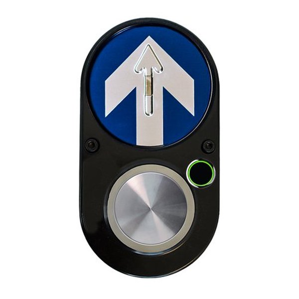
Modern pedestrian push buttons often use touch or proximity sensors.
Pedestrian safety is paramount. A push button is provided for pedestrians to request a crossing. When the button is pressed:
- The system logs the request.
- At the next safe opportunity (usually after the current green light cycle for vehicles completes its minimum duration and transitions through yellow), vehicle traffic in all directions is halted with red lights.
- The pedestrian "Walk" signal (Green LED) is activated for a predefined duration.
- After the "Walk" period, the pedestrian signal returns to "Don't Walk" (Red LED), and normal vehicle traffic resumes.
Traffic Light States and Transitions
The core of the system's logic is a state machine. It cycles through states like "Road 1 Green," "Road 1 Yellow," "Road 2 Green," "Road 2 Yellow," and "Pedestrian Walk." Transitions between states are triggered by:
- Timers expiring (e.g., green light duration).
- Vehicle detection (though simplified in this example, it can be used to extend green times).
- Pedestrian button presses.
millis() for timing instead of delay() allows the Arduino to remain responsive to sensor inputs and button presses even while waiting for a time period to elapse.
Visualizing System Interactions: A Mindmap
To better understand how the different parts of the system connect and interact, the following mindmap illustrates the relationships between the Arduino, sensors, lights, and the overall operational flow.
This mindmap shows the Arduino as the central controller, processing inputs from IR sensors and the pedestrian button, and managing outputs to the various traffic and pedestrian LEDs based on its programmed logic and state transitions.
Arduino Code for Smart Traffic Control
Here is the complete Arduino sketch for controlling a two-road traffic signal with pedestrian clearance. This code defines the pin connections, sets up the timing, and implements the state machine logic.
// Pin Definitions for Traffic Signal Controller

// Road 1 Traffic Lights
const int R1_RED_LED = 5;    // Red LED for Road 1
const int R1_YELLOW_LED = 6; // Yellow LED for Road 1
const int R1_GREEN_LED = 7;  // Green LED for Road 1

// Road 2 Traffic Lights
const int R2_RED_LED = 8;    // Red LED for Road 2
const int R2_YELLOW_LED = 9; // Yellow LED for Road 2
const int R2_GREEN_LED = 10; // Green LED for Road 2

// Pedestrian Signal
const int PED_RED_LED = 11;     // "Don't Walk" LED (Red)
const int PED_GREEN_LED = 12;   // "Walk" LED (Green)
const int PED_BUTTON = 4;       // Push button for pedestrian request

// IR Sensors for Vehicle Detection
const int IR_SENSOR_ROAD1 = 2;  // IR sensor for Road 1
const int IR_SENSOR_ROAD2 = 3;  // IR sensor for Road 2

// Timing Constants (in milliseconds)
const unsigned long GREEN_DURATION_VEHICLE = 10000; // 10 seconds for vehicle green
const unsigned long YELLOW_DURATION_VEHICLE = 3000; // 3 seconds for vehicle yellow
const unsigned long PED_WALK_DURATION = 7000;       // 7 seconds for pedestrian walk
const unsigned long ALL_RED_DELAY = 1000;         // 1 second all red for safety clearance before pedestrian walk

// State Machine Variables
enum TrafficState {
  R1_GREEN_R2_RED,    // Road 1 Green, Road 2 Red
  R1_YELLOW_R2_RED,   // Road 1 Yellow, Road 2 Red
  R2_GREEN_R1_RED,    // Road 2 Green, Road 1 Red
  R2_YELLOW_R1_RED,   // Road 2 Yellow, Road 1 Red
  PED_CROSSING_START, // All vehicle lights red, preparing for pedestrian walk
  PED_WALK            // Pedestrian walk signal active
};
TrafficState currentState;
unsigned long lastStateChangeTime = 0;    // Time of the last state transition
unsigned long pedestrianRequestTime = 0;  // Time when pedestrian button was last pressed
bool pedestrianIsWaiting = false;       // Flag to indicate a pending pedestrian request

void setup() {
  // Initialize Serial for debugging (optional, remove if not needed)
  Serial.begin(9600);
  Serial.println("Traffic Control System Initializing...");

  // Setup LED pins as OUTPUT
  pinMode(R1_RED_LED, OUTPUT);
  pinMode(R1_YELLOW_LED, OUTPUT);
  pinMode(R1_GREEN_LED, OUTPUT);
  pinMode(R2_RED_LED, OUTPUT);
  pinMode(R2_YELLOW_LED, OUTPUT);
  pinMode(R2_GREEN_LED, OUTPUT);
  pinMode(PED_RED_LED, OUTPUT);
  pinMode(PED_GREEN_LED, OUTPUT);

  // Setup IR sensor pins as INPUT
  // Assuming the IR sensor module outputs LOW when an object is detected
  pinMode(IR_SENSOR_ROAD1, INPUT);
  pinMode(IR_SENSOR_ROAD2, INPUT);

  // Setup Pedestrian button pin as INPUT_PULLUP
  // The button should connect the pin to GND when pressed
  pinMode(PED_BUTTON, INPUT_PULLUP);

  // Initial state: Road 1 Green, Road 2 Red, Pedestrian Don't Walk
  setRoad1Lights(LOW, LOW, HIGH); // Args: Red, Yellow, Green state (HIGH = ON)
  setRoad2Lights(HIGH, LOW, LOW); // Args: Red, Yellow, Green state
  setPedestrianLights(HIGH, LOW);   // Args: Ped Red (Don't Walk), Ped Green (Walk)
  currentState = R1_GREEN_R2_RED;
  lastStateChangeTime = millis();
  Serial.println("System Initialized: Road 1 Green, Road 2 Red, Pedestrian Don't Walk.");
}

void loop() {
  unsigned long currentTime = millis(); // Get the current time

  // Check for pedestrian button press
  // digitalRead(PED_BUTTON) will be LOW if pressed due to INPUT_PULLUP
  if (digitalRead(PED_BUTTON) == LOW) {
    if (!pedestrianIsWaiting) { // Only register if not already waiting
      pedestrianIsWaiting = true;
      pedestrianRequestTime = currentTime; // Record the time of request
      Serial.println("Pedestrian button pressed. Request logged.");
    }
  }

  // Read IR Sensors (simplified logic: LOW means vehicle detected)
  bool vehicleOnRoad1 = (digitalRead(IR_SENSOR_ROAD1) == LOW);
  bool vehicleOnRoad2 = (digitalRead(IR_SENSOR_ROAD2) == LOW);

  // --- State Machine Logic ---
  switch (currentState) {
    case R1_GREEN_R2_RED:
      setRoad1Lights(LOW, LOW, HIGH); // Road 1 Green ON
      setRoad2Lights(HIGH, LOW, LOW); // Road 2 Red ON
      setPedestrianLights(HIGH, LOW);   // Pedestrian Don't Walk ON

      // Transition to Yellow for Road 1 if:
      // 1. Green light duration has passed OR
      // 2. A pedestrian is waiting (and some minimal green time passed for current traffic)
      if ((currentTime - lastStateChangeTime >= GREEN_DURATION_VEHICLE) ||
          (pedestrianIsWaiting && (currentTime - pedestrianRequestTime > 1000))) { // Ensure button press isn't immediate cause if light just turned green
        currentState = R1_YELLOW_R2_RED;
        lastStateChangeTime = currentTime;
        Serial.println("State Change: R1_GREEN -> R1_YELLOW_R2_RED");
      }
      break;

    case R1_YELLOW_R2_RED:
      setRoad1Lights(LOW, HIGH, LOW); // Road 1 Yellow ON
      setRoad2Lights(HIGH, LOW, LOW); // Road 2 Red ON
      setPedestrianLights(HIGH, LOW);   // Pedestrian Don't Walk ON

      if (currentTime - lastStateChangeTime >= YELLOW_DURATION_VEHICLE) {
        if (pedestrianIsWaiting) {
          currentState = PED_CROSSING_START; // Prioritize pedestrian
          Serial.println("State Change: R1_YELLOW -> PED_CROSSING_START (Pedestrian waiting)");
        } else {
          currentState = R2_GREEN_R1_RED; // No pedestrian, switch to Road 2
          Serial.println("State Change: R1_YELLOW -> R2_GREEN_R1_RED");
        }
        lastStateChangeTime = currentTime;
      }
      break;

    case R2_GREEN_R1_RED:
      setRoad1Lights(HIGH, LOW, LOW); // Road 1 Red ON
      setRoad2Lights(LOW, LOW, HIGH); // Road 2 Green ON
      setPedestrianLights(HIGH, LOW);   // Pedestrian Don't Walk ON

      if ((currentTime - lastStateChangeTime >= GREEN_DURATION_VEHICLE) ||
          (pedestrianIsWaiting && (currentTime - pedestrianRequestTime > 1000))) {
        currentState = R2_YELLOW_R1_RED;
        lastStateChangeTime = currentTime;
        Serial.println("State Change: R2_GREEN -> R2_YELLOW_R1_RED");
      }
      break;

    case R2_YELLOW_R1_RED:
      setRoad1Lights(HIGH, LOW, LOW); // Road 1 Red ON
      setRoad2Lights(LOW, HIGH, LOW); // Road 2 Yellow ON
      setPedestrianLights(HIGH, LOW);   // Pedestrian Don't Walk ON

      if (currentTime - lastStateChangeTime >= YELLOW_DURATION_VEHICLE) {
        if (pedestrianIsWaiting) {
          currentState = PED_CROSSING_START; // Prioritize pedestrian
          Serial.println("State Change: R2_YELLOW -> PED_CROSSING_START (Pedestrian waiting)");
        } else {
          currentState = R1_GREEN_R2_RED; // No pedestrian, switch back to Road 1
          Serial.println("State Change: R2_YELLOW -> R1_GREEN_R2_RED");
        }
        lastStateChangeTime = currentTime;
      }
      break;

    case PED_CROSSING_START:
      // Ensure all vehicle lights are red before pedestrian walk
      setRoad1Lights(HIGH, LOW, LOW); // Road 1 Red ON
      setRoad2Lights(HIGH, LOW, LOW); // Road 2 Red ON
      setPedestrianLights(HIGH, LOW);   // Pedestrian Don't Walk ON (briefly or ensure it is)

      if (currentTime - lastStateChangeTime >= ALL_RED_DELAY) { // Wait for intersection to clear
        currentState = PED_WALK;
        lastStateChangeTime = currentTime;
        Serial.println("State Change: PED_CROSSING_START -> PED_WALK");
      }
      break;

    case PED_WALK:
      setRoad1Lights(HIGH, LOW, LOW); // Vehicles Red
      setRoad2Lights(HIGH, LOW, LOW); // Vehicles Red
      setPedestrianLights(LOW, HIGH);   // Pedestrian Walk (Green) ON

      if (currentTime - lastStateChangeTime >= PED_WALK_DURATION) {
        pedestrianIsWaiting = false; // Reset pedestrian request flag

        // After pedestrian crossing, decide which road gets green next.
        // Simple logic: default to Road 1, or Road 2 if vehicles are waiting there and not on Road 1.
        // More complex logic could check IR sensors for demand.
        if (vehicleOnRoad2 && !vehicleOnRoad1) {
             currentState = R2_GREEN_R1_RED;
             Serial.println("State Change: PED_WALK -> R2_GREEN_R1_RED (Vehicles on R2)");
        } else {
             currentState = R1_GREEN_R2_RED; // Default to Road 1 Green
             Serial.println("State Change: PED_WALK -> R1_GREEN_R2_RED (Defaulting to R1)");
        }
        lastStateChangeTime = currentTime;
      }
      break;
  }
}

// Helper function to control Road 1 lights
// Pass HIGH to turn an LED ON, LOW to turn it OFF
void setRoad1Lights(bool r_state, bool y_state, bool g_state) {
  digitalWrite(R1_RED_LED, r_state);
  digitalWrite(R1_YELLOW_LED, y_state);
  digitalWrite(R1_GREEN_LED, g_state);
}

// Helper function to control Road 2 lights
void setRoad2Lights(bool r_state, bool y_state, bool g_state) {
  digitalWrite(R2_RED_LED, r_state);
  digitalWrite(R2_YELLOW_LED, y_state);
  digitalWrite(R2_GREEN_LED, g_state);
}

// Helper function to control Pedestrian lights
void setPedestrianLights(bool r_state, bool g_state) {
  digitalWrite(PED_RED_LED, r_state);     // Don't Walk signal
  digitalWrite(PED_GREEN_LED, g_state);   // Walk signal
}
Understanding the Code
Pin Definitions and Constants:
At the beginning, const int variables are used to assign names to Arduino pins for LEDs and sensors, making the code easier to read and modify. Timing constants like GREEN_DURATION_VEHICLE define how long each light phase lasts.
State Machine (enum TrafficState):
An enum (enumeration) defines the different states of the traffic light system (e.g., R1_GREEN_R2_RED, PED_WALK). The currentState variable holds the current operational state.
setup() Function:
This function runs once when the Arduino starts. It initializes serial communication (for debugging), sets the pin modes (INPUT for sensors/button, OUTPUT for LEDs), and sets the initial traffic light state.
loop() Function:
This function runs continuously. It checks the current time using millis(), reads sensor inputs, and manages state transitions based on the switch (currentState) block. This non-blocking approach ensures the Arduino remains responsive.
Pedestrian Logic:
When PED_BUTTON is pressed (reads LOW due to INPUT_PULLUP), pedestrianIsWaiting becomes true. The state machine then prioritizes moving to the PED_CROSSING_START and PED_WALK states at the next safe interval.
Helper Functions:
Functions like setRoad1Lights(), setRoad2Lights(), and setPedestrianLights() simplify controlling the LEDs for different roads and pedestrian signals, making the main loop cleaner.
Comparing Traffic Control Approaches
The IR sensor-based system offers significant advantages over traditional fixed-timer systems, especially in adaptability and pedestrian safety. However, more advanced systems like those using AI and IoT can offer even greater efficiencies. The radar chart below provides a comparative overview of these approaches based on several key attributes. A higher score (towards the edge of the chart) generally indicates a better performance or more desirable characteristic for that attribute (e.g., higher efficiency, lower cost).
As seen in the chart, while fixed-timer systems are cheaper and simpler, they lack adaptability. The IR sensor system provides a good balance. Advanced AI/IoT systems excel in performance but come with higher costs and complexity.
Watch it in Action: IR Sensor Traffic Light Demo
Visualizing how these components work together can be very helpful. The video below demonstrates a traffic light system controlled by Arduino and IR sensors, similar in principle to the project described. It showcases vehicle detection and signal changes, providing a practical look at what you can achieve.
This video (and similar tutorials available online) can offer inspiration and practical insights as you build and troubleshoot your own smart traffic signal.
Frequently Asked Questions (FAQ)
Recommended Further Exploration
To deepen your understanding and explore more advanced concepts, consider these related queries:
- How to implement adaptive green light timing based on IR sensor vehicle counts with Arduino.
- Integrating multiple Arduino traffic controllers for synchronized intersections.
- Using ESP32 for IoT-enabled traffic management with remote monitoring.
- Advanced pedestrian detection techniques for smart crosswalks using Arduino.
References
This response was synthesized using information from various sources, including the following relevant articles and projects:
Last updated May 18, 2025