
Bridging Worlds: Unlock Seamless Communication Between Arduino and PLCs
Discover the methods, protocols, and tools to integrate the flexibility of Arduino with the robustness of industrial PLCs.
Highlights
- Multiple Communication Pathways: Connect Arduino and PLCs using various methods like Serial (RS232/RS485), Modbus (RTU/TCP), Ethernet, or direct Digital I/O, depending on application needs and hardware capabilities.
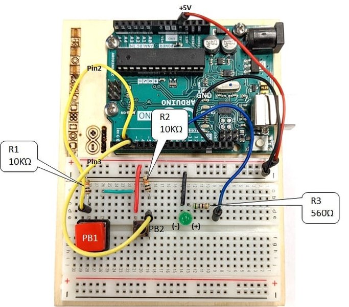
- Hardware Interfacing is Key: Successfully linking devices requires careful attention to voltage level differences (e.g., 5V Arduino vs. 24V PLC) using level shifters (relays, optocouplers) and establishing a common ground connection.
- Leverage Standard Protocols & Tools: Utilize industry-standard protocols like Modbus for reliable data exchange and consider tools like the Arduino PLC IDE for simplified programming and integration, especially with compatible Arduino hardware.
Understanding the Arduino-PLC Integration Challenge
Integrating Arduino microcontrollers with Programmable Logic Controllers (PLCs) offers a powerful combination: Arduino's flexibility, affordability, and vast community support complement the PLC's industrial robustness, reliability, and standard compliance. However, these devices operate differently. Arduino typically uses 5V or 3.3V TTL logic and C/C++ programming, while PLCs often employ 24V logic levels and programming standards like IEC 61131-3 (including Ladder Logic). Bridging this gap requires careful consideration of hardware interfacing and communication protocols.
Essential Hardware Considerations
Before establishing communication, addressing the physical connection and electrical compatibility is crucial:
Voltage Level Differences
Arduinos operate at lower voltages (typically 5V, sometimes 3.3V) compared to the 24V standard common in industrial PLC I/O. Directly connecting a 24V PLC output to an Arduino input without protection will damage the Arduino. Similarly, a 5V Arduino output might not be sufficient to trigger a 24V PLC input.
- Solution: Use level-shifting techniques. Relays or optocouplers provide electrical isolation and can switch higher voltages based on lower voltage signals, protecting both devices. Voltage dividers can step down PLC output voltage for Arduino inputs, but isolation methods are generally safer in industrial environments. Some PLCs might offer low-voltage input modules compatible with Arduino signals.
Common Ground Connection
For reliable signal transmission, especially with serial or direct digital connections, both the Arduino and the PLC must share a common ground reference. Without it, voltage levels become relative and communication can be unreliable or fail completely.
- Action: Ensure the ground pins (GND) of the Arduino and the PLC power supply are connected. This is fundamental for most direct electrical communication methods.
Choosing Your Communication Method
Several methods exist to facilitate data exchange between Arduino and PLCs. The best choice depends on the application's complexity, required data rate, distance, environmental noise, and the specific capabilities of the Arduino and PLC models.
1. Direct Digital I/O Communication
Simplicity for Basic Signaling
This is the most basic method, using digital input and output pins to send simple ON/OFF status signals between the devices. For example, a PLC output can trigger an Arduino input, or an Arduino output can signal a PLC input.
- Implementation: Requires careful wiring and voltage level adaptation (using relays or optocouplers) as described in the hardware considerations.
- Use Case: Simple status indication, basic triggering (e.g., start/stop signals), presence detection.
- Limitation: Only suitable for binary information; cannot transfer complex data like sensor values or text.
2. Serial Communication (RS232 / RS485)
Point-to-Point Data Exchange
Serial communication allows for transmitting more complex data byte by byte over dedicated transmit (Tx) and receive (Rx) lines.
- RS232: Suitable for short distances (up to ~15 meters) and point-to-point connections. Requires level conversion (e.g., MAX232 chip or module) to interface Arduino's TTL serial signals (often pins D0/D1) with the PLC's RS232 port. Connect Tx of one device to Rx of the other, and vice versa.
- RS485: More robust for industrial environments, supports longer distances (up to 1200 meters), and allows multiple devices (multi-drop) on a single bus (typically using A/B lines). Requires an RS485 transceiver module (e.g., MAX485 based) connected to Arduino's serial pins. This is often the physical layer used for Modbus RTU.
- Configuration: Both devices must be configured with matching communication parameters: baud rate, data bits, parity, and stop bits.
- Use Case: Sending sensor readings, commands, or status updates between a single PLC and Arduino.
Example interface showing Ladder Logic, a common PLC programming language often used alongside Arduino integration.
3. Modbus Protocol (RTU & TCP)
The Industrial Standard
Modbus is a widely adopted, open serial communication protocol standard in industrial automation. It defines a message structure for devices to request and provide data using a master-slave or client-server relationship.
- Modbus RTU: Uses serial communication (typically RS485 for robustness, but RS232 is also possible) as the physical layer. Arduino can be programmed as either a Modbus master (requesting data from PLC) or slave (providing data to PLC) using available libraries (e.g., `ModbusMaster`, `ModbusRTU`). Requires an appropriate serial interface (RS485 module).
- Modbus TCP: Uses Ethernet (TCP/IP) as the communication layer. Arduino requires an Ethernet shield or built-in Ethernet capability. The PLC must also support Modbus TCP. This allows communication over standard network infrastructure. Arduino libraries (e.g., `ModbusTCP`) are available.
- Implementation: Requires configuring device addresses (for slaves), register maps (defining data locations), and communication parameters. The Arduino PLC IDE provides built-in support for setting up Modbus communication on compatible boards like Opta and Portenta.
- Use Case: Reading/writing sensor values, controlling actuators, exchanging status information in industrial or building automation systems.
4. Ethernet / Network Communication
Leveraging Network Infrastructure
Beyond Modbus TCP, Arduino and PLCs equipped with Ethernet ports can communicate using other network protocols.
- Methods: Custom TCP/IP or UDP messaging can be implemented for specific needs. Other industrial Ethernet protocols might be supported depending on the PLC and potentially specific Arduino shields/libraries (though less common for standard Arduinos).
- Hardware: Arduino needs an Ethernet shield (like W5500, ENC28J60) or built-in Ethernet. Both devices connect to the same network via switches or direct cables.
- Configuration: Requires setting up IP addresses, subnet masks, and ports on both devices.
- Use Case: Applications requiring integration into existing Ethernet networks, higher data throughput, or more complex network interactions. Wi-Fi and Bluetooth options may also be available on specific Arduino boards (like Portenta) for wireless communication.
5. Industrial Fieldbuses (PROFIBUS, CAN Bus)
Integration into Specific Industrial Networks
Some PLCs heavily rely on specific industrial fieldbuses.
- PROFIBUS: Common with Siemens PLCs. Integrating Arduino often requires an RS485 interface for the physical layer (PROFIBUS DP) and careful configuration. This typically involves treating the Arduino as a custom slave device. A GSD (Geräte Stammdaten) file describing the Arduino device might need to be imported into the PLC's engineering software (e.g., Siemens TIA Portal or Step 7) to configure communication.
- CAN Bus: A robust bus common in automotive and industrial applications. Arduino can communicate over CAN bus using a CAN transceiver module/shield. The Arduino PLC IDE provides tutorials and support for CAN communication on compatible hardware.
- Implementation: Requires specific hardware interfaces (shields/modules) and protocol-specific programming on the Arduino. Configuration on the PLC side is also necessary.
- Use Case: Integrating Arduino into existing PROFIBUS or CAN networks for specialized sensing or control tasks.
Comparing Communication Methods
Choosing the right method involves trade-offs. This chart provides a comparative overview of common Arduino-PLC communication methods based on several key factors. Note that these are generalized ratings for typical implementations.
This chart visually summarizes the trade-offs: Digital I/O is simple and cheap but very limited. Serial options offer moderate complexity. Modbus (especially TCP) and fieldbuses offer high robustness and data handling suitable for industrial use but can be more complex or costly to implement.
Software and Programming Tools
Establishing communication requires programming on both the Arduino and the PLC side.
Arduino Side
- Standard Arduino IDE: Use C/C++ with relevant libraries for the chosen communication method (e.g., `Serial` for basic serial, `Ethernet.h` for Ethernet, various Modbus libraries like `ArduinoModbus`, `ModbusMaster`).
- Arduino PLC IDE: A specialized IDE designed for industrial applications using compatible Arduino hardware (like Opta PLC, Portenta Machine Control). It supports programming using IEC 61131-3 standards (Ladder Diagram, Function Block Diagram, etc.) alongside standard Arduino sketches. It offers built-in support and tutorials for industrial protocols like Modbus (RTU/TCP), CAN bus, and network communication, simplifying integration. It also allows sharing variables between the PLC logic environment and the Arduino sketch environment.
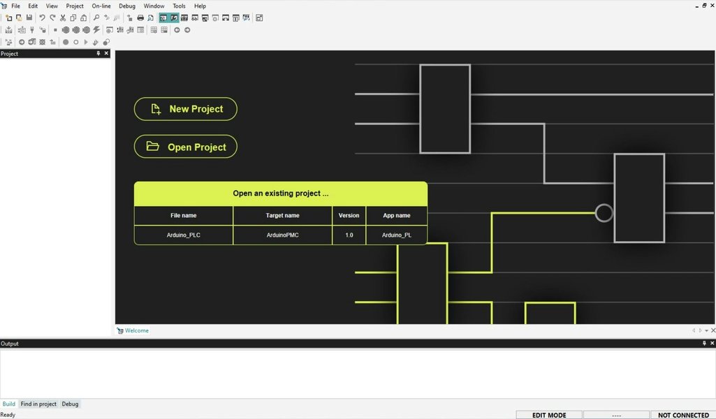
The Arduino PLC IDE provides an environment tailored for industrial control applications.
PLC Side
- PLC Programming Software: Use the vendor-specific software (e.g., Siemens TIA Portal, Rockwell Studio 5000, Schneider EcoStruxure Control Expert). Configure the PLC's communication ports (Serial, Ethernet) and use built-in function blocks or instructions to handle the chosen protocol (e.g., Modbus Master/Slave blocks, serial communication blocks).
- Hardware Configuration: For protocols like PROFIBUS, you may need to add the Arduino (represented by a GSD file) to the hardware configuration within the PLC software.
General Steps to Establish Communication
- Choose the Method: Select the most appropriate communication method (Serial, Modbus, Ethernet, etc.) based on your PLC/Arduino capabilities, application requirements, and environment.
- Hardware Connection: Wire the devices correctly. Connect communication lines (Tx/Rx, A/B, Ethernet cable) and ensure a common ground. Implement necessary level shifting (relays, optocouplers) if interfacing different voltage levels directly.
- Configure Parameters: Set matching communication parameters on both devices. For serial: baud rate, data bits, parity, stop bits. For Ethernet: IP addresses, subnet masks, ports. For Modbus: Slave IDs, register addresses.
- Program Arduino: Write the Arduino code using appropriate libraries to implement the chosen protocol (e.g., initialize serial port, set up Modbus slave/master, configure Ethernet connection).
- Program PLC: Configure the PLC's communication interface and program logic to send/receive data using the chosen protocol (e.g., configure Modbus communication blocks, read/write to serial port).
- Test and Debug: Start with simple tests (e.g., sending a known value, toggling a digital signal). Use serial monitors, PLC diagnostic tools, and network sniffers (for Ethernet) to troubleshoot issues. Check wiring, parameters, and code logic systematically.
Visualizing Arduino-PLC Communication Options
This mindmap provides a visual overview of the key aspects involved in connecting Arduino and PLC devices.
(5V/3.3V vs 24V)"] id1b["Level Shifting
(Relays, Optocouplers)"] id1c["Common Ground"] id1d["Wiring
(Tx/Rx, A/B, Ethernet)"] id1e["Shields/Modules
(RS485, Ethernet, CAN)"] id2["Communication Methods"] id2a["Digital I/O"] id2b["Serial"] id2b1["RS232"] id2b2["RS485"] id2c["Modbus"] id2c1["Modbus RTU
(Serial - RS485/RS232)"] id2c2["Modbus TCP
(Ethernet)"] id2d["Ethernet/Network"] id2d1["TCP/IP"] id2d2["UDP"] id2e["Industrial Fieldbus"] id2e1["PROFIBUS-DP"] id2e2["CAN Bus"] id3["Software & Programming"] id3a["Arduino Side"] id3a1["Arduino IDE + Libraries
(Serial, Modbus, Ethernet)"] id3a2["Arduino PLC IDE
(IEC 61131-3, Opta, Portenta)"] id3b["PLC Side"] id3b1["Vendor Software
(TIA Portal, Studio 5000)"] id3b2["Communication Blocks"] id3b3["Hardware Configuration
(GSD Files)"] id4["Key Considerations"] id4a["Protocol Choice"] id4b["Parameter Matching
(Baud Rate, IP Address)"] id4c["Master/Slave Roles"] id4d["Testing & Debugging"]
The mindmap illustrates the interconnectedness of hardware setup, choosing the right communication protocol (like Serial or Modbus), and utilizing the appropriate software tools on both the Arduino and PLC sides.
Practical Example: Modbus RTU Communication
Modbus RTU over RS485 is a very common and reliable method for Arduino-PLC communication in industrial settings. The video below demonstrates setting up this type of communication, which involves connecting an Arduino to a PLC using an RS485 interface and configuring both devices to exchange data using the Modbus RTU protocol.
This video typically covers the necessary hardware connections (Arduino, RS485 module, PLC), Arduino programming using a Modbus library (often setting the Arduino as a Modbus slave), and PLC programming (setting the PLC as a Modbus master to read from or write to the Arduino's registers). Key steps usually involve defining Modbus addresses, register maps, and ensuring matching serial communication parameters (baud rate, parity, etc.).
Summary Table of Communication Protocols
This table summarizes the main communication methods discussed, highlighting their key characteristics:
| Protocol/Method | Physical Layer | Typical Use Case | Pros | Cons |
|---|---|---|---|---|
| Digital I/O | Direct Wire (with level shifting) | Simple binary signals (On/Off) | Very simple, low cost | Only binary data, needs voltage adaptation |
| RS232 Serial | RS232 (Point-to-point) | Short-distance data exchange | Simple protocol, widely available | Short distance, susceptible to noise, point-to-point only |
| RS485 Serial | RS485 (Multi-drop Bus) | Longer distance, multi-device serial comms | Long distance, noise resistant, multi-drop | Requires specific transceivers, half-duplex typically |
| Modbus RTU | RS485 / RS232 | Standard industrial data exchange | Industry standard, robust, widely supported | Relatively slow, requires careful configuration |
| Modbus TCP | Ethernet | Networked industrial data exchange | Uses standard Ethernet, faster than RTU, flexible | Requires Ethernet hardware, slightly more complex setup |
| PROFIBUS-DP | RS485 (typically) | Integration into Siemens environments | Fast, deterministic, industrial standard | Complex setup for non-native devices, requires GSD files |
| CAN Bus | CAN (Differential Pair) | Real-time control, automotive, industrial | Robust, real-time capable, error handling | Requires CAN transceivers/controllers, specific libraries |
Frequently Asked Questions (FAQ)
Recommended Reading
- Explore a detailed guide on setting up Modbus RTU between an Arduino and a Siemens PLC.
- Learn specific techniques for handling voltage level differences when connecting Arduino digital I/O pins to a PLC.
- Discover the features and benefits of using the Arduino PLC IDE for industrial automation projects.
- Understand the differences and trade-offs between Modbus TCP and Modbus RTU for Arduino-PLC communication scenarios.
References
Last updated May 3, 2025