
Distance Calculation in Multi-Sector BD-RIS Systems
A Comprehensive Guide on Using Azimuth and Polar Angles in Hexagonal Geometries
Key Insights
- Coordinate Transformation: Converting spherical coordinates (distance, azimuth, polar/elevation) into Cartesian coordinates is central.
- Trigonometric Computation: Use of sine and cosine functions to extract x, y, and z components followed by Euclidean distance calculation.
- Hexagonal Sector Considerations: Understanding the geometry of hexagonal cells and sector boundaries is key to proper positioning and distance estimation.
Understanding the Geometry and Coordinate Systems
In a multi-sector Beyond Diagonal Reconfigurable Intelligent Surface (BD-RIS) assisted communication system, especially when employing a six-sector or hexagonal cell layout, the position of both the transmitter and user is often best described in a 3D coordinate system. Such systems use spherical coordinates for positioning – these include a distance (or radius), an azimuth (horizontal) angle, and a polar (vertical or elevation) angle.
Spherical and Cartesian Coordinates
A point within a three-dimensional space can be defined via spherical coordinates as follows:
- r: Represents the radial distance from the origin, i.e., the transmitter.
- Azimuth Angle (θ): The angle measured in the horizontal plane, typically from a reference direction such as North.
- Polar Angle (φ): The angle measured from the vertical axis (commonly known as the elevation angle).
The corresponding transformation from spherical to Cartesian coordinates is given by:
Transformation Equations
Using the following formulas, we compute the x, y, and z coordinates:
\( x = r \cdot \sin(\phi) \cdot \cos(\theta) \)
\( y = r \cdot \sin(\phi) \cdot \sin(\theta) \)
\( z = r \cdot \cos(\phi) \)
Here, \(r\) is the distance from the transmitter (assumed as the origin) to the point where the user is located. Converting user coordinates from spherical to Cartesian form is an important step because it allows us to employ the Euclidean distance formula.
Hexagonal Sector Configuration
When you consider a hexagonal or six-sector partitioning of the coverage area, the geometry becomes slightly more complex.
Hexagonal Cell Geometry
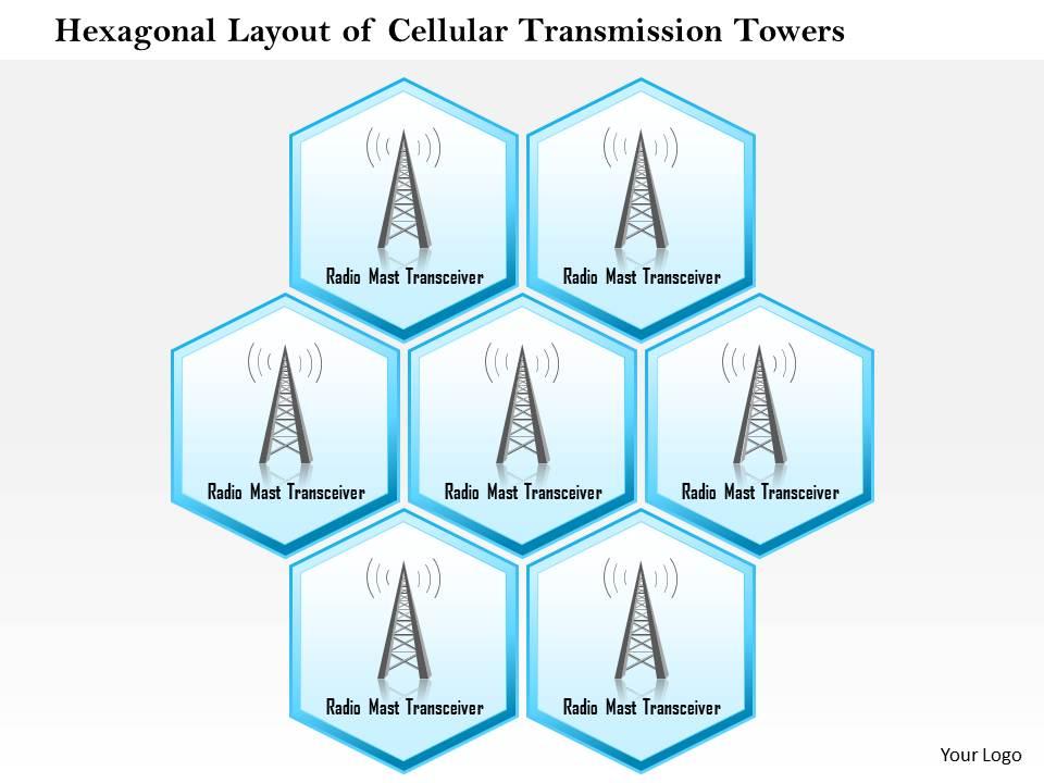
In cellular communications, cells are often assumed hexagonal for simplicity and effective coverage planning. A few key points include:
- Central Point: The transmitter is typically located at the center of the hexagon.
- Sector Boundaries: When the cell is divided into six equal sectors, each sector spans a central angle of 60°.
- Adjacent Cell Distance: The distance between centers of adjacent cells is often computed based on the relationship with the hexagon's radius, though for calculating the transmitter–user distance the radial distance within a single cell is of prime relevance.
Handling the Angles in a Multi-Sector Environment
The user’s positioning within a particular sector is determined by their azimuth angle relative to the transmitter. If the sector boundaries are set at 60-degree intervals (for six sectors), the exact sector in which the user resides can be determined by comparing the user's azimuth with the boundary limits. Though polar angles are more significant in 3D positioning, especially when there is an elevation component (e.g., aerial users or multi-story environments), azimuth assists in deciding the horizontal sector placement.
Distance Calculation Methodology
Step-by-Step Calculation
The following steps provide a structured approach to determine the distance between a transmitter and a user:
Step 1: Coordinate Conversion
Begin by representing the user’s position in spherical coordinates:
- Given distance \( r \) (which may be unknown and subject to solving the problem in reverse in some cases),
- Azimuth angle \( \theta \) (in degrees or radians), and
- Polar angle \( \phi \) (in degrees or radians).
Convert these spherical coordinates into Cartesian coordinates using:
\( x = r \cdot \sin(\phi) \cdot \cos(\theta) \)
\( y = r \cdot \sin(\phi) \cdot \sin(\theta) \)
\( z = r \cdot \cos(\phi) \)
Step 2: Euclidean Distance Computation
Once you have the Cartesian coordinates of both the transmitter and the user, calculate the Euclidean distance between these two points:
\( \text{distance} = \sqrt{(x_u - x_t)^2 + (y_u - y_t)^2 + (z_u - z_t)^2} \)
Here, \((x_t, y_t, z_t)\) are the coordinates of the transmitter (often at the origin in an idealized scenario) and \((x_u, y_u, z_u)\) represent the user’s Cartesian coordinates as derived from their spherical coordinates.
Step 3: Sector and Boundary Considerations
In a hexagonal layout, the geometry of each sector can impose practical limits on user positioning. While the pure Euclidean distance holds good mathematically, in a cellular system:
- Determine the sector in which the user lies based on their azimuth angle relative to the center of the hexagon.
- Adjust distance calculations if the user is near the boundaries or overlapping adjacent cells.
- Utilize additional methods such as triangulation if precise positioning is critical and if multiple sector stations or reflective surfaces (BD-RIS elements) are involved.
Consideration for 3D vs 2D Scenarios
In standard terrestrial communication, a 2D approximation might suffice, but in BD-RIS systems that cater to complex environments (with high-rise buildings or aerial vehicles), incorporating the polar angle becomes essential:
For 3D path calculations:
\( x = r \cdot \sin(\phi) \cdot \cos(\theta) \)
\( y = r \cdot \sin(\phi) \cdot \sin(\theta) \)
\( z = r \cdot \cos(\phi) \)
In a 2D model, if elevation differences are negligible, you may consider simply using the projection on the horizontal plane, which simplifies distance calculation to:
\( \text{distance}_{2D} = \sqrt{(x_u - x_t)^2 + (y_u - y_t)^2} \)
Practical Implementation and Simulation
In simulation models for BD-RIS assisted systems, integration of these calculations is a core aspect. Here, a joint design of transmit precoders and RIS matrices enhances the overall system performance, and accurate distance estimation based on user angle and position plays a vital role.
Implementing in a Simulation Model
Consider the following simplified Python code to illustrate the 3D transformation and distance computation:
# Convert angles from degrees to radians
import math

def to_cartesian(r, theta_deg, phi_deg):
    theta = math.radians(theta_deg)   # Azimuth angle in radians
    phi = math.radians(phi_deg)         # Polar (elevation) angle in radians
    x = r * math.sin(phi) * math.cos(theta)
    y = r * math.sin(phi) * math.sin(theta)
    z = r * math.cos(phi)
    return x, y, z

# Example positions
# Transmitter assumed at origin (0, 0, 0)
transmitter = (0, 0, 0)
# User position defined by spherical coordinates
r_user = 100  # distance in meters
azimuth_user = 30  # degrees
polar_user = 45    # degrees (elevation)
user = to_cartesian(r_user, azimuth_user, polar_user)

# Euclidean distance calculation
def euclidean_distance(point1, point2):
    return math.sqrt((point1[0]-point2[0])<b>2 +
                     (point1[1]-point2[1])</b>2 +
                     (point1[2]-point2[2])**2)

distance = euclidean_distance(transmitter, user)
print("The distance between the transmitter and user is:", distance)
In practice, the user’s location might be derived through complex triangulation methods which leverage multiple measurements across different sectors. The BD-RIS setup especially may use advanced beamforming techniques to modify effective path lengths and maximize signal quality.
Comparison Summary Table
| Aspect | Description | Formula/Method |
|---|---|---|
| Coordinate System | Spherical (r, θ, φ) converted to Cartesian (x, y, z) for calculation | \(x = r\sin(\phi)\cos(\theta)\), \(y = r\sin(\phi)\sin(\theta)\), \(z = r\cos(\phi)\) |
| Distance Calculation | Euclidean distance between transmitter and user | \( \sqrt{(x_2 - x_1)^2 + (y_2 - y_1)^2 + (z_2 - z_1)^2} \) |
| Sector Layout | Hexagonal cells, each spanning 60° for six sectors | Determine user sector via azimuth boundaries |
| Simulation Implementation | Python code to illustrate coordinate conversion and distance computation | See code above |
Advanced Considerations in BD-RIS Assisted Systems
Incorporating RIS Effects and Beamforming
In BD-RIS assisted communication, reconfigurable surfaces are employed to enhance or redirect signal propagation beyond traditional line-of-sight paths. When calculating distances:
- Measurements might include additional path delays or effective distance adjustments due to RIS reflections. This requires joint optimization via transmit precoder and RIS matrix designs.
- The calculated distance from geometric coordinates still serves as the baseline from which advanced algorithms adapt the beamforming to optimize channel quality.
- Practical systems can employ iterative techniques where real-time adjustments are based on user positions within the hexagon and the relative angles.
Additional Geometric Techniques
Sometimes using polar coordinate distance formulas directly offers a simplified model. For instance, if both the transmitter and the user are located at known radial distances from a common origin, the distance can also be determined using:
\( \text{distance} = \sqrt{r_1^2 + r_2^2 - 2r_1r_2\cos(\Delta \theta)} \)
where \( \Delta \theta \) represents the difference in the azimuth angles. However, for accurate 3D scenarios that include elevation differences, reverting to Cartesian conversions and employing Euclidean space functions is recommended.
References
- Spherical Coordinate System - Wikipedia
- Azimuth - Wikipedia
- Azimuth Calculator - Omni Calculator
- Distance Calculation with Polar Coordinates - Math StackExchange
- Transmitter Side Beyond-Diagonal Reconfigurable Intelligent Surface - IEEE Xplore
Recommended Queries
Last updated March 17, 2025