
Unlocking the Secrets of Boolean Expressions: From Equation to Truth Table
Crafting Logical Circuits from Boolean Expressions with Symbols and Truth Tables
Key Highlights: Understanding Boolean Expressions
- Boolean expressions are fundamental in digital electronics and computer science for representing logical operations.
- A truth table systematically maps all possible input combinations to their corresponding output, providing a comprehensive view of a circuit's behavior.
- Logic gate symbols offer a visual representation of Boolean operations, simplifying circuit design and analysis.
Deconstructing the Boolean Expression: S = ((A + B) * C) * D
To effectively construct a logic diagram and truth table for the expression \(S = ((A + B) \cdot C) \cdot D\), we need to break it down into manageable parts. This expression involves logical OR (denoted by +) and logical AND (denoted by \(\cdot\)).
Step 1: Understanding the Logical Operators
First, let's clarify the operations:
- OR (+): The OR operation (\(A + B\)) is true if either A or B (or both) are true.
- AND (\(\cdot\)): The AND operation \(((A + B) \cdot C)\) is true only if both \((A + B)\) and \(C\) are true.
Step 2: Constructing the Logic Diagram
The logic diagram visually represents the Boolean expression using standard logic gate symbols. Here's how it translates:
- A OR B: This part requires an OR gate with inputs A and B.
- (A + B) AND C: The output of the OR gate is then fed into an AND gate along with input C.
- ((A + B) * C) AND D: Finally, the output of the second AND gate is fed into another AND gate along with input D.
Step 3: Building the Truth Table
The truth table enumerates all possible combinations of inputs (A, B, C, D) and their corresponding output S. Since we have four inputs, there will be \(2^4 = 16\) rows in the truth table.
Let's define intermediate signals to make the table clearer:
- \(X = A + B\)
- \(Y = X \cdot C = (A + B) \cdot C\)
- \(S = Y \cdot D = ((A + B) \cdot C) \cdot D\)
Truth Table for S = ((A + B) * C) * D
Below is the truth table, mapping each input combination to the final output S:
| A | B | C | D | X = A + B | Y = (A + B) * C | S = ((A + B) * C) * D |
|---|---|---|---|---|---|---|
| 0 | 0 | 0 | 0 | 0 | 0 | 0 |
| 0 | 0 | 0 | 1 | 0 | 0 | 0 |
| 0 | 0 | 1 | 0 | 0 | 0 | 0 |
| 0 | 0 | 1 | 1 | 0 | 0 | 0 |
| 0 | 1 | 0 | 0 | 1 | 0 | 0 |
| 0 | 1 | 0 | 1 | 1 | 0 | 0 |
| 0 | 1 | 1 | 0 | 1 | 1 | 0 |
| 0 | 1 | 1 | 1 | 1 | 1 | 1 |
| 1 | 0 | 0 | 0 | 1 | 0 | 0 |
| 1 | 0 | 0 | 1 | 1 | 0 | 0 |
| 1 | 0 | 1 | 0 | 1 | 1 | 0 |
| 1 | 0 | 1 | 1 | 1 | 1 | 1 |
| 1 | 1 | 0 | 0 | 1 | 0 | 0 |
| 1 | 1 | 0 | 1 | 1 | 0 | 0 |
| 1 | 1 | 1 | 0 | 1 | 1 | 0 |
| 1 | 1 | 1 | 1 | 1 | 1 | 1 |
This truth table comprehensively details the behavior of the Boolean expression for all possible inputs.
Visualizing Logic Gates
Logic gates are the fundamental building blocks of digital circuits. Each gate performs a specific Boolean operation. Understanding the symbols and behavior of these gates is crucial for designing and analyzing digital systems.
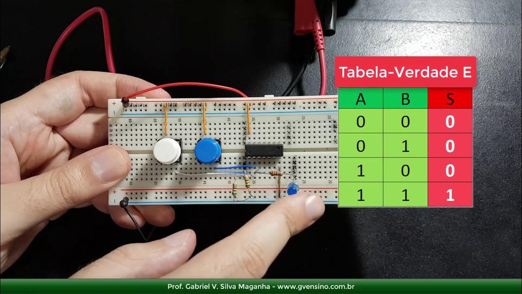
These images represent common logic gates and their symbolic representations. From left to right:
- The first image shows the AND and OR gates, fundamental components in digital logic.
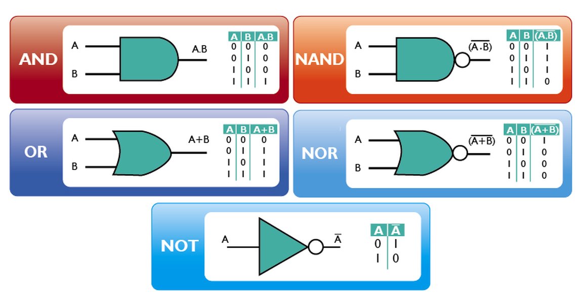
- The second image illustrates various logic gates including AND, OR, NOT, NAND, and NOR.
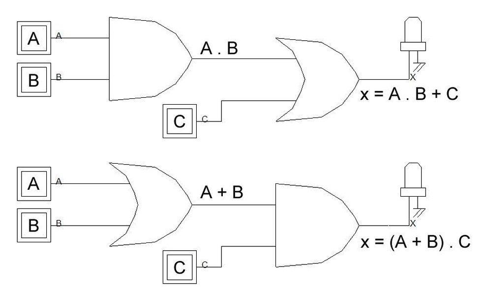
- The third image visually connects logic circuits, Boolean expressions, and truth tables.
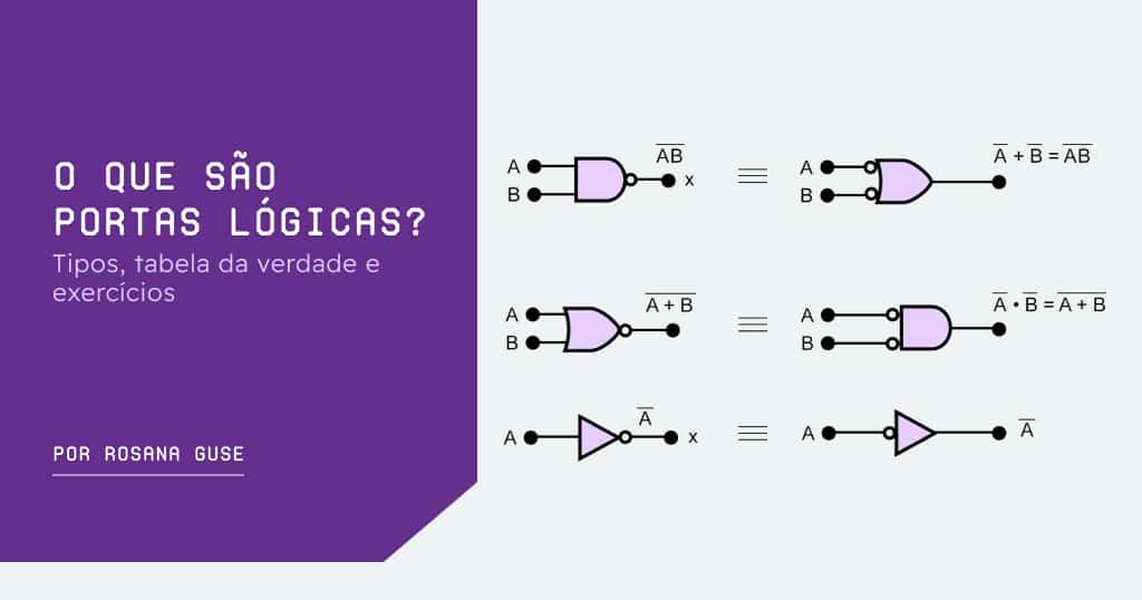
- The fourth image displays the layout of logic gates, truth tables, and related exercises.
These gates manipulate binary inputs to produce a binary output, forming the basis for complex digital operations. Understanding these symbols is essential for designing and interpreting digital circuits.
Bringing Boolean Expressions to Life
This video, "Aula I - Expressões Booleanas, Circuitos Lógicos e Tabela," offers an introduction to Boolean expressions, logic circuits, and truth tables. This is particularly relevant because it visually explains how these concepts are interconnected and provides a foundational understanding of how to convert Boolean expressions into functional circuits. The video enhances the understanding of the relationships between logical expressions and their practical implementations.
Simplifying Boolean Algebra
Boolean algebra provides tools and theorems that allow for the simplification of complex Boolean expressions. Simplification is crucial in digital logic design as it leads to simpler circuits with fewer components, reducing cost and complexity.
Key Laws and Theorems in Boolean Algebra
- Commutative Law: \(A + B = B + A\) and \(A \cdot B = B \cdot A\)
- Associative Law: \((A + B) + C = A + (B + C)\) and \((A \cdot B) \cdot C = A \cdot (B \cdot C)\)
- Distributive Law: \(A \cdot (B + C) = (A \cdot B) + (A \cdot C)\) and \(A + (B \cdot C) = (A + B) \cdot (A + C)\)
- Identity Law: \(A + 0 = A\) and \(A \cdot 1 = A\)
- Complement Law: \(A + \neg A = 1\) and \(A \cdot \neg A = 0\)
- Idempotent Law: \(A + A = A\) and \(A \cdot A = A\)
- Absorption Law: \(A + (A \cdot B) = A\) and \(A \cdot (A + B) = A\)
- DeMorgan's Law: \(\neg (A + B) = \neg A \cdot \neg B\) and \(\neg (A \cdot B) = \neg A + \neg B\)
Applying Boolean Algebra to Simplify Expressions
Using these laws, complex expressions can be simplified. Simplified expressions translate to circuits that require fewer logic gates, making them more efficient and cost-effective.
For example, consider the expression \(S = ((A + B) \cdot C) \cdot D\). While this expression is already relatively simple, understanding these laws allows for more complex expressions to be optimized significantly.
Benefits of Simplification
-
Reduced Circuit Complexity: Simplification leads to fewer logic gates.
-
Lower Costs: Fewer components reduce the overall cost of the circuit.
-
Improved Performance: Simpler circuits can operate faster and more reliably.
FAQ: Boolean Expressions and Logic Diagrams
References
Last updated April 10, 2025