
Bridging Worlds: Building RF Bridges for VOR Systems and Testing Applications
Understanding the distinctions between RF bridges and VOR navigation systems can unlock powerful tools for radio frequency testing and analysis
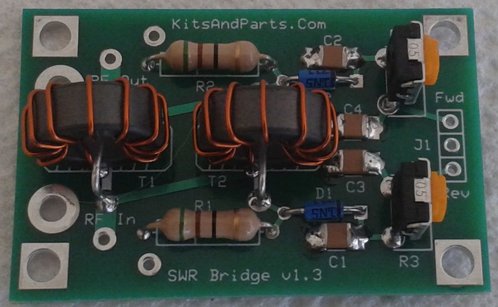
Essential Insights on RF Bridges & VOR Systems
- Important Distinction: VOR (Very High Frequency Omnidirectional Range) is an aviation navigation system, while RF bridges are test instruments for measuring impedance, SWR, or return loss.
- Key Applications: RF bridges enable precise antenna tuning and component testing with minimal signal output, making them valuable for amateur radio operators and RF engineers.
- Construction Complexity: While standard RF bridges can be built as DIY projects, actual VOR systems require advanced engineering expertise and specialized equipment.
Understanding RF Bridges vs. VOR Systems
There appears to be a fundamental distinction that needs clarification regarding your query. A VOR (Very High Frequency Omnidirectional Range) system and an RF bridge are two different technologies with distinct purposes:
RF Bridges: Test & Measurement Tools
RF bridges are electronic test instruments used primarily for impedance matching, antenna tuning, and signal reflection measurements. Common types include:
- Return Loss Bridges - measure reflected signal power
- SWR Bridges - measure standing wave ratio for antenna systems
- Impedance Bridges - determine unknown impedance values
- Noise Bridges - use noise sources for impedance measurements
VOR Systems: Aviation Navigation Technology
VOR is a sophisticated radio navigation system used in aviation that allows aircraft to determine their position by receiving radio signals transmitted by a network of ground radio beacons. These systems:
- Operate in the VHF band (108-117.95 MHz)
- Provide azimuth information to aircraft
- Use complex phase comparison techniques
- Require specialized equipment and engineering expertise to build
The Technical Connection
While VOR systems do contain RF components and circuits that might use bridge configurations internally, a "VOR RF bridge" is not a standard term in RF engineering. It's likely you're interested in either building a test instrument for VOR systems or understanding how RF bridges work in relation to VOR technology.
The mindmap above illustrates the relationship and distinctions between RF bridges and VOR systems, showing how they represent different branches of RF technology with distinct applications and complexity levels.
Building a Basic RF Bridge for Testing
If you're interested in building an RF bridge for testing purposes (which could potentially be used to test VOR-related equipment), here's how to construct a simple return loss bridge:
Components Required
| Component | Specification | Purpose |
|---|---|---|
| Resistors | 50 ohm and 250 ohm (precision) | Bridge circuit elements |
| Toroid Core | FT37-43 or similar | For balun transformer |
| Copper Wire | 26-30 AWG enameled | Transformer windings |
| RF Connectors | SMA, BNC, or UHF | Signal input/output |
| Enclosure | Metal preferred | Shielding and housing |
Construction Steps
1. Prepare the Balun Transformer
The balun (balanced-to-unbalanced) transformer is crucial for the bridge operation:
- Wind 10 turns of enameled copper wire around the toroid core
- Create a center tap by twisting a loop in the middle of the winding
- Apply a thin coating of clear nail polish to secure the windings
2. Assemble the Bridge Circuit
Follow this configuration:
- Connect one 250 ohm resistor between the RF input and the detector output
- Connect another 250 ohm resistor between ground and the detector output
- Connect the 50 ohm resistor between the RF input and the DUT (Device Under Test) port
- Connect the balun transformer between the DUT port and detector output
3. Housing and Connections
- Mount all components in a metal enclosure for proper shielding
- Keep all connections as short as possible to minimize stray inductance
- Use high-quality RF connectors for reliable measurements
- Consider adding ferrite beads on external connections to prevent unwanted RF pickup
The chart above illustrates the relative construction complexity of different RF bridges compared to a complete VOR system. As shown, RF bridges are significantly less complex to build than a full VOR navigation system.
Using an RF Bridge for Testing
Basic Operation Principles
Once constructed, your RF bridge functions based on these principles:
- The bridge circuit balances when the impedance of the device under test matches the reference impedance (typically 50 ohms)
- Any mismatch between these impedances creates an imbalance that produces an output signal
- The magnitude of this output signal indicates the degree of mismatch
Testing Procedure
To use your RF bridge effectively:
- Connect an RF signal source (typically 1-30 MHz) to the input port
- Connect the device under test (antenna, filter, etc.) to the DUT port
- Connect a detector (spectrum analyzer, oscilloscope, or RF power meter) to the detector port
- Adjust the device under test until you achieve minimum output on the detector
- This minimum indicates the point of best impedance match
Applications for Your RF Bridge
Antenna Testing and Tuning
Your RF bridge excels at:
- Finding resonant frequency of antennas
- Adjusting matching networks for optimal performance
- Verifying antenna bandwidth
Component Testing
Use your bridge to:
- Determine the impedance of RF components
- Test filters for proper frequency response
- Evaluate transmission lines for discontinuities
Limitations to Consider
Be aware that your DIY RF bridge:
- May have frequency limitations (typically works best below 200 MHz)
- Requires calibration for accurate measurements
- Can be affected by nearby metal objects or strong RF fields
This video tutorial demonstrates the construction of a return loss bridge, which is one type of RF bridge that can be built for testing RF circuits and antennas.
Understanding VOR Systems
If your interest lies in VOR systems specifically, it's important to understand that building a complete VOR navigation system is beyond the scope of most DIY projects due to:
VOR System Components
- Complex antenna arrays for omnidirectional signal transmission
- Precision phase control circuits to generate variable and reference signals
- High-power RF amplifiers for adequate coverage range
- Sophisticated monitoring systems to ensure signal accuracy
- Standardized equipment that meets strict aviation regulations
How VOR Systems Work
VOR systems operate based on these principles:
- A VOR ground station transmits two signals: a reference phase signal and a variable phase signal
- The reference signal is omnidirectional and provides a timing baseline
- The variable signal's phase shifts according to the azimuth direction
- Aircraft receivers compare these phases to determine their bearing relative to the station
Educational Approach
While building a full VOR system isn't practical, you could create a simplified demonstration model using:
- Arduino or similar microcontroller to generate timing signals
- Basic RF modules operating in the VHF range
- Small antenna array to demonstrate directional principles
- Software to visualize the phase relationships
Frequently Asked Questions
References
- RF Bridge Construction Guide - VK4AMZ
- Building and Using the RF Noise Bridge - GlobalSpec Reference
- Build a Return Loss Bridge - QSL.net
- Radio Aids to Aircraft Navigation - RF Cafe
- A Simple Wideband Return Loss Bridge - YagiCAD
Recommended Explorations
Last updated March 29, 2025