
Crafting Your Definitive Chapter on the CAN Bus System: A Comprehensive Guide
Unlock the intricacies of the Controller Area Network with this detailed roadmap for your graduation project chapter.
Embarking on a chapter about the Controller Area Network (CAN) bus system for your graduation project is an excellent endeavor, especially since it's central to your work. This guide will provide you with a comprehensive structure, detailed content suggestions, and relevant resources to help you craft an insightful and thorough 12-page chapter. My knowledge cutoff is today's date, Thursday, 2025-05-22.
Chapter Highlights: Key Insights into CAN Bus
- Robust Foundation: Understand how CAN bus, originally developed by Bosch, revolutionized in-vehicle networking by reducing wiring complexity and enhancing reliability through a two-wire differential signaling system.
- Intelligent Communication: Explore the intricacies of CAN messaging, including its frame structure, priority-based arbitration mechanism (lower ID wins), and sophisticated error detection and handling capabilities that ensure data integrity.
- Versatile Applications & Evolution: Discover the widespread use of CAN bus beyond automotive, in industrial automation, aerospace, and medical fields, and learn about its evolution with CAN FD (Flexible Data-Rate) to meet modern high-bandwidth demands.
Below is a suggested structure and content plan designed to help you develop a compelling and informative chapter, approximately 12 pages in length.
Proposed Chapter Title: The Controller Area Network (CAN) Bus: Principles, Implementation, and Impact in Modern Systems
1. Unveiling CAN Bus: Origins and Core Purpose (Approx. 1-1.5 pages)
Setting the Stage for Understanding
Begin your chapter by introducing the Controller Area Network (CAN) bus. Define it as a robust vehicle bus standard designed to allow microcontrollers and devices to communicate with each other's applications without a host computer. Discuss its historical context: developed by Robert Bosch GmbH in the early 1980s, primarily to address the increasing complexity and weight of electrical wiring in automobiles. Explain that its official release was in 1986, followed by ISO standardization (ISO 11898) in 1993.
Highlight the motivation behind its development – the need to replace complex, dedicated point-to-point wiring systems with a simplified, multiplexed communication network. Briefly touch upon its significance in your specific graduation project, explaining how understanding CAN bus is crucial for your work. Conclude this section by outlining what the reader will learn in the subsequent parts of the chapter.
2. The Backbone of CAN: Physical Architecture and Topology (Approx. 2 pages)
Understanding the Hardware Foundation
This section should delve into the physical aspects of the CAN bus. Describe its typical physical layer, which consists of a two-wire (twisted pair) bus: CAN High (CANH) and CAN Low (CANL). Explain the principle of differential signaling, where the logical state of the bus is determined by the voltage difference between CANH and CANL. This makes the bus highly resistant to electromagnetic interference and common-mode noise, a critical feature for harsh automotive and industrial environments.
Discuss the bus topology, where all nodes (Electronic Control Units or ECUs) are connected in parallel to these two wires. Detail the importance of termination resistors (typically 120 Ω) at each end of the main bus line to prevent signal reflections and ensure signal integrity. You can also mention the concepts of dominant (logical '0') and recessive (logical '1') bits, and how a dominant bit will always overwrite a recessive bit on the bus.
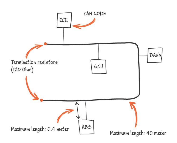
A typical CAN bus wiring schematic showing two nodes connected via CANH and CANL lines with termination resistors.
Nodes and Their Roles
Explain that each node connected to the CAN bus requires a CAN controller (to handle the protocol logic like framing and error checking) and a CAN transceiver (to adapt the signal levels between the CAN controller and the physical bus lines). This decentralized architecture means there's no single master controlling the bus; any node can transmit data if the bus is free.
3. The Language of the Network: CAN Message Frames (Approx. 2 pages)
Decoding CAN Communication
Detail the structure of a CAN message frame, which is the fundamental unit of communication. Explain that CAN is a message-based protocol, not an address-based one. This means messages are broadcast to all nodes, and each node decides if the message is relevant to it based on the message's identifier (ID).
Describe the main fields of a standard CAN frame (CAN 2.0A, 11-bit identifier) and an extended CAN frame (CAN 2.0B, 29-bit identifier):
- Start of Frame (SOF): Marks the beginning of a message.
- Arbitration Field: Contains the message Identifier (ID) and the Remote Transmission Request (RTR) bit. The ID determines the message's priority.
- Control Field: Specifies the number of data bytes in the data field.
- Data Field: Contains the actual data, up to 8 bytes for Classical CAN.
- CRC Field (Cyclic Redundancy Check): Used for error detection.
- ACK Field (Acknowledge): Used by receiving nodes to indicate successful reception.
- End of Frame (EOF): Marks the end of the message.
Introduce the different types of CAN frames:
- Data Frame: Carries data from a transmitter to receivers.
- Remote Frame: Sent by a node to request the transmission of a specific Data Frame from another node.
- Error Frame: Transmitted by any node that detects a bus error.
- Overload Frame: Used by a node to request extra delay between messages if it's too busy.
Comparing Classical CAN and CAN FD
This is a good place to introduce a table comparing Classical CAN with its successor, CAN FD (Flexible Data-Rate), highlighting advancements in data payload and speed.
| Feature | Classical CAN (CAN 2.0A/B) | CAN FD (Flexible Data-Rate) |
|---|---|---|
| Max Data Payload | 8 bytes | Up to 64 bytes |
| Max Data Rate (Data Phase) | Up to 1 Mbit/s | Up to 5 Mbit/s (or higher, depending on transceiver and network design) |
| Frame Structure | Fixed bit rate for entire frame | Dual bit rate: slower for arbitration phase, faster for data phase |
| Identifier Length | 11-bit (Standard) or 29-bit (Extended) | 11-bit (Standard) or 29-bit (Extended) |
| Error Detection | Robust (CRC, ACK, Bit Monitoring, Stuffing) | Enhanced (improved CRC algorithms for larger payloads) |
| Compatibility | - | CAN FD controllers are typically backward compatible with Classical CAN. Classical CAN nodes cannot interpret CAN FD frames. |
This table illustrates how CAN FD addresses some limitations of Classical CAN, particularly for applications requiring higher bandwidth and larger data transfers.
4. Maintaining Order: Arbitration and Error Resilience (Approx. 2 pages)
Collision-Free Communication
Explain the non-destructive bitwise arbitration process, a cornerstone of CAN. When multiple nodes attempt to transmit simultaneously, the node sending the message with the numerically lowest identifier (highest priority) wins arbitration and continues transmitting without interruption or data loss. Nodes that lose arbitration switch to receive mode and will attempt to retransmit later. This mechanism ensures that the most critical messages are prioritized.
Robust Error Detection and Fault Confinement
CAN bus incorporates several mechanisms for error detection and fault confinement, contributing to its high reliability:
- Bit Monitoring: Transmitting nodes monitor the bus level to detect discrepancies between the bit sent and the bit observed.
- Bit Stuffing: After five consecutive bits of the same polarity, an opposite polarity bit is inserted to ensure enough edges for synchronization and prevent errors. A violation of this rule indicates a "stuff error."
- Frame Check (CRC): The transmitter calculates a CRC checksum for the message, and receivers do the same. A mismatch indicates a "CRC error."
- Acknowledgement Check (ACK): Transmitting nodes expect an acknowledgement from at least one receiving node. Lack of acknowledgement indicates an "ACK error."
- Form Check: Checks for violations in the fixed-format parts of a CAN frame, indicating a "form error."
Describe how nodes that detect errors transmit an Error Frame, alerting all other nodes. Also, explain fault confinement: CAN controllers can distinguish between temporary disturbances and permanent failures, and can even disconnect themselves from the bus (bus-off state) if they persistently cause errors, preventing a faulty node from crippling the entire network.
5. Why CAN Reigns: Key Advantages and Strengths (Approx. 1.5-2 pages)
The Enduring Appeal of CAN Bus
Summarize the main advantages that have made CAN bus a dominant standard:
- Robustness and Reliability: Excellent noise immunity due to differential signaling and sophisticated error handling mechanisms make it suitable for safety-critical applications.
- Reduced Wiring Complexity and Cost: Multiplexing reduces the amount of wiring needed, saving weight, space, and cost compared to traditional point-to-point connections.
- Prioritization of Messages: The ID-based arbitration ensures that high-priority data (e.g., engine control, braking) gets bus access when needed.
- Decentralized Control: No single master node means the system can continue to operate even if some nodes fail.
- Flexibility and Scalability: Nodes can be easily added or removed from the bus without extensive reprogramming of other nodes.
- Standardization: Wide adoption and ISO standardization ensure interoperability and a broad ecosystem of tools and components.
- Real-Time Performance: While not the fastest, its deterministic arbitration provides predictable communication times suitable for many real-time control tasks.
CAN Bus Performance Profile: A Comparative Look
This radar chart offers a visual comparison of CAN bus (Classical) against other common in-vehicle networking protocols based on several key performance indicators. This is an opinionated analysis for illustrative purposes.
This chart visually represents how CAN bus excels in robustness and cost-effectiveness, while newer protocols might offer higher speeds or larger data payloads. The values (1-10 scale) are illustrative.
6. CAN Bus in Motion: A World of Applications (Approx. 2 pages)
Automotive: The Birthplace and Primary Domain
CAN bus is ubiquitous in modern vehicles. Detail its use in connecting various ECUs for functions like:
- Powertrain Control: Engine management, transmission control, emissions systems.
- Chassis Control: Anti-lock Braking Systems (ABS), Electronic Stability Program (ESP), active suspension.
- Body Electronics: Power windows, door locks, seats, lighting, climate control (HVAC).
- Driver Assistance: Airbags, parking assist, cruise control.
- Infotainment Systems: Dashboard displays, audio systems (though often supplemented by other buses like MOST).
- Diagnostics: The On-Board Diagnostics (OBD-II) port in vehicles often uses CAN (ISO 15765-4) for diagnostic communication.

Conceptual representation of various ECUs connected via CAN bus in an automotive system.
Beyond the Automobile: Industrial and Other Sectors
Expand on CAN's versatility. Its robustness and real-time capabilities have led to adoption in:
- Industrial Automation: Factory automation, robotics, motion control, embedded machine control. Higher-layer protocols like CANopen are common here.
- Aerospace: Flight-state sensors, navigation systems, engine control systems.
- Maritime: Ship automation, navigation (NMEA 2000 is based on CAN).
- Medical Equipment: Medical devices, hospital automation.
- Building Automation: Elevators, HVAC systems.
- Agricultural Machinery: Tractors and farming equipment (ISOBUS is based on J1939/CAN).
- Household Appliances: Some high-end appliances.
This video, "Fundamentals of CAN Bus in vehicles - A deep dive into the protocol," offers an excellent overview of CAN bus technology and its pivotal role in automotive communication, making complex concepts accessible.
The video above provides a visual and auditory explanation of CAN bus principles, reinforcing the concepts discussed and illustrating its practical importance, especially within vehicular systems. It can help visualize how different components interact over the network.
7. Charting the Course: Higher-Layer Protocols & Future Horizons (Approx. 1.5-2 pages)
Standardizing Functionality: Higher-Layer Protocols
Explain that CAN bus itself defines the physical and data link layers (Layers 1 and 2 of the OSI model). For specific application domains, higher-layer protocols (HLPs) are built on top of CAN to define aspects like message content, network management, and device profiles. Briefly introduce some key HLPs:
- CANopen: Widely used in industrial automation, medical devices, and embedded systems. Defines device profiles and communication objects.
- SAE J1939: Standard for commercial vehicles (trucks, buses, agricultural machinery). Defines message formats and parameters for vehicle data.
- NMEA 2000: Used in marine electronics for interconnecting sensors and display units on ships and boats.
- ISO 15765 (Diagnostics on CAN / DoCAN): Specifies diagnostic communication over CAN, forming part of OBD-II.
- Unified Diagnostic Services (UDS - ISO 14229): A diagnostic protocol used in ECUs, often over CAN.
The Evolving Landscape: Limitations and CAN FD
Discuss the limitations of Classical CAN, primarily its maximum data rate of 1 Mbit/s and the 8-byte payload, which are becoming insufficient for modern applications demanding more bandwidth (e.g., advanced driver-assistance systems (ADAS), high-resolution displays).
Introduce CAN FD (Flexible Data-Rate) as an evolution. As previously tabled, CAN FD allows for higher data rates (up to 5 Mbit/s or more in the data phase) and larger message payloads (up to 64 bytes). This makes it a suitable upgrade path for many systems. Mention its growing adoption and how it helps extend the life of CAN-based architectures.
You might also briefly touch upon other emerging technologies like Automotive Ethernet, which complements CAN by handling very high bandwidth requirements, while CAN continues to be used for control and real-time tasks.
Visualizing the CAN Bus Ecosystem
This mindmap provides a conceptual overview of the CAN bus system, branching out into its core components, communication principles, applications, and evolution. It helps to visually connect the various topics discussed in this chapter.
(CANH/CANL, Twisted Pair)"] id1b["Topology
(Bus, Nodes, Termination)"] id1c["Differential Signaling"] id1d["Dominant/Recessive Bits"] id2["Communication Protocol"] id2a["Message-Based"] id2b["Frames Types
(Data, Remote, Error, Overload)"] id2c["Frame Structure
(ID, DLC, Data, CRC, ACK)"] id2d["Arbitration
(ID-based Priority)"] id2e["Error Handling
(Detection, Confinement)"] id3["Key Characteristics"] id3a["Advantages
(Robust, Cost-Effective, Flexible, Real-Time)"] id3b["Limitations
(Speed, Payload - Classical)"] id4["Applications"] id4a["Automotive
(ECUs, Powertrain, Body, Diagnostics)"] id4b["Industrial
(Automation, Robotics)"] id4c["Aerospace & Maritime"] id4d["Medical Devices"] id5["Evolution & HLPs"] id5a["CAN FD
(Flexible Data-Rate)"] id5b["Higher-Layer Protocols
(CANopen, J1939, NMEA 2000, UDS)"] id5c["Future Trends
(ADAS, IoT Integration)"]
8. Conclusion: Synthesizing Knowledge and Project Relevance (Approx. 0.5-1 page)
Bringing It All Together
Conclude your chapter by summarizing the key aspects of the CAN bus system. Reiterate its importance as a robust and reliable communication protocol that has fundamentally shaped in-vehicle and industrial networking. Emphasize its enduring relevance despite the emergence of newer technologies, particularly with advancements like CAN FD. Briefly restate how a solid understanding of CAN bus is vital for your graduation project and how the principles discussed in the chapter apply to your specific implementation or analysis.
Frequently Asked Questions (FAQ)
What is the main advantage of CAN bus's differential signaling?
How does CAN bus handle message collisions?
What is the difference between CAN 2.0A and CAN 2.0B?
Why are termination resistors necessary in a CAN bus network?
Conclusion
This comprehensive chapter outline provides a robust framework for discussing the CAN bus system. By detailing its history, physical architecture, communication protocols, error handling, applications, and future evolution, you can effectively demonstrate a thorough understanding of this critical technology for your graduation project. Remember to weave in specific examples and connections to your own project work throughout the chapter to enhance its relevance and impact.
Recommended Further Exploration
- What are the detailed performance differences and migration strategies when moving from Classical CAN to CAN FD?
- How can security vulnerabilities in CAN bus networks be addressed, and what are the best practices for secure CAN communication?
- What are common CAN bus troubleshooting techniques and which software/hardware tools are most effective for diagnosing network issues?
- What are the specific differences in application, message structure, and network management between major higher-layer CAN protocols like CANopen, J1939, and NMEA 2000?