
Understanding Poor Insertion Loss Margin in Cat6 Cable Testing
Comprehensive Guide to Diagnosing and Improving Cat6 Cable Performance
Key Takeaways
- Insertion loss margin is crucial for maintaining signal integrity in Cat6 cables.
- Compliance with ANSI/TIA-568 standards ensures optimal cable performance.
- Improving insertion loss involves using high-quality materials and adhering to best installation practices.
What is Insertion Loss Margin?
Insertion loss margin refers to the difference between the measured signal loss in a cable and the maximum allowable loss as defined by industry standards. In the context of Cat6 cables, which are designed for high-speed data transmission up to frequencies of 250 MHz and beyond, maintaining an adequate insertion loss margin is essential for ensuring reliable and efficient network performance.
Understanding Insertion Loss
Insertion loss is the reduction in signal power as it travels through a cable. It is typically measured in decibels (dB) and represents how much of the signal is lost between the transmitter and receiver. A higher insertion loss indicates greater signal degradation, which can adversely affect data transmission quality and speed.
Interpreting Poor Insertion Loss Margin
A poor insertion loss margin means that the actual signal loss in the cable is close to the maximum limit specified by the relevant standard. This leaves little room for additional losses that might occur due to factors like cable length, connector quality, or environmental conditions. Consequently, even minor deviations can result in the cable failing to meet performance requirements, leading to issues such as reduced data rates, increased error rates, and overall network instability.
Standards for Testing Cat6 Cables
Ensuring that Cat6 cables meet the necessary performance criteria involves adhering to established industry standards. The primary standards governing the testing and certification of Cat6 cables include:
ANSI/TIA-568 Standards
The ANSI/TIA-568 series of standards, particularly ANSI/TIA-568-C.2 and its successor ANSI/TIA-568.2-D, provide comprehensive guidelines for the performance requirements of twisted-pair cabling systems, including Cat6. These standards specify the acceptable limits for various parameters, including insertion loss, return loss, crosstalk, and more, across a range of frequencies up to 250 MHz.
Key Aspects of ANSI/TIA-568
- Frequency Range: Specifications cover signal transmission up to 250 MHz to support high-speed data applications.
- Performance Metrics: Define acceptable levels for insertion loss, return loss, near-end crosstalk (NEXT), and other critical parameters.
- Testing Procedures: Outline standardized methods for measuring and certifying cable performance using professional-grade testing equipment.
Other Relevant Standards
In addition to ANSI/TIA-568, other standards and guidelines may influence Cat6 cable performance, including IEEE standards for networking and various international standards for cable manufacturing and installation practices.
Causes of Poor Insertion Loss Margin
Several factors can contribute to a reduced insertion loss margin in Cat6 cables. Understanding these causes is essential for diagnosing issues and implementing effective solutions.
1. Cable Quality
The quality of the Cat6 cable itself is paramount. Lower-quality cables may use inferior materials, have inconsistent twisting of wire pairs, or suffer from manufacturing defects, all of which can increase insertion loss. Opting for cables from reputable manufacturers that adhere to industry standards can help mitigate this issue.
2. Cable Length
Longer cable runs inherently experience more signal attenuation. Although Cat6 cables are designed to support lengths up to 100 meters, exceeding this limit can significantly degrade signal quality, reducing the insertion loss margin.
3. Installation Practices
Improper installation techniques can introduce additional insertion loss. Common installation mistakes include:
- Exceeding the recommended bend radius, leading to micro-bends or macro-bends that increase attenuation.
- Applying excessive pulling tension during cable runs, causing physical strain and potential damage to the cable.
- Crushing or pinching cables within conduits or cable trays, which can disrupt signal transmission.
4. Connector and Termination Quality
Poorly manufactured or improperly installed connectors can introduce significant insertion loss. Ensuring that connectors are of high quality and that terminations are performed correctly is essential for maintaining a healthy insertion loss margin.
5. Environmental Factors
External conditions such as temperature extremes, humidity, and electromagnetic interference can affect cable performance. High temperatures, in particular, can increase the resistance of conductors, leading to higher insertion loss.
6. Physical Damage
Any physical damage to the cable, such as cuts, abrasions, or kinks, can compromise the integrity of the conductors and insulation, resulting in increased signal loss.
How to Improve Insertion Loss Margin
Enhancing the insertion loss margin involves a combination of selecting high-quality components, adhering to best installation practices, and performing regular maintenance and testing. Below are detailed strategies to improve the insertion loss margin in Cat6 cabling systems.
1. Use High-Quality Cables
Investing in high-quality Cat6 cables from reputable manufacturers ensures that the materials and construction meet or exceed industry standards. Features to look for include:
- Solid Copper Conductors: These offer better conductivity and lower insertion loss compared to stranded conductors.
- Consistent Twist Rates: Properly twisted wire pairs reduce crosstalk and signal degradation.
- Shielded Designs: Shielded Twisted Pair (STP) or Shielded and Foiled Twisted Pair (SFTP) cables can provide better protection against electromagnetic interference (EMI).
2. Optimize Cable Length
Maintaining cable lengths within the recommended maximum of 100 meters for Cat6 cables is crucial. If longer runs are necessary, consider using active equipment such as switches or repeaters to boost the signal, thereby preserving the insertion loss margin.
3. Adhere to Proper Installation Practices
Ensuring that cables are installed correctly can significantly reduce insertion loss. Key practices include:
- Maintain Bend Radius: Follow manufacturer guidelines for minimum bend radius to prevent micro-bends and macro-bends.
- Avoid Excessive Tension: Use appropriate pulling techniques and tools to prevent over-stressing the cable during installation.
- Prevent Cable Crushing: Properly secure cables within conduits and cable trays to avoid pinching and crushing.
4. Ensure Quality Connectors and Terminations
Using high-quality connectors and performing precise terminations are essential for minimizing insertion loss. Best practices include:
- Using connectors that are specifically designed for Cat6 performance.
- Following manufacturer instructions meticulously during termination.
- Inspecting terminations with visual and testing tools to ensure proper contact and alignment.
5. Control Environmental Factors
Managing the operating environment can help maintain optimal cable performance. Strategies include:
- Installing cables in environments with controlled temperature and humidity.
- Using temperature-rated cables for areas prone to heat exposure.
- Implementing shielding and grounding techniques to reduce susceptibility to EMI.
6. Regular Testing and Maintenance
Performing routine testing and maintenance ensures that any issues affecting the insertion loss margin are identified and addressed promptly. This includes:
- Using professional-grade cable testers to measure insertion loss and other critical parameters.
- Calibrating testing equipment regularly to maintain measurement accuracy.
- Inspecting cables for physical damage and performing corrective actions as needed.
7. Reduce Connection Points
Minimizing the number of connection points in a cable run can help lower overall insertion loss. Each additional connector or splice introduces potential points of signal degradation. Whenever possible, design cabling systems with as few connections as necessary to maintain signal integrity.
8. Choose Low-Loss Components
Selecting components that contribute minimally to signal loss can enhance the insertion loss margin. This includes:
-
Using high-quality patch panels and jacks designed for low attenuation.
-
Employing low-loss patch cords and adapters.
Practical Steps to Diagnose and Improve Insertion Loss
Implementing a systematic approach to diagnosing and improving insertion loss can lead to more effective and sustainable network performance. The following steps outline a practical method for addressing poor insertion loss margin in Cat6 cabling systems.
Step 1: Conduct a Comprehensive Cable Test
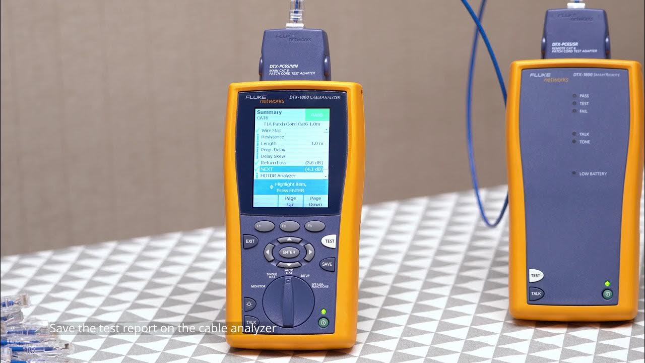
Begin by performing a thorough cable test using a professional-grade cable analyzer. This will provide detailed measurements of insertion loss, return loss, crosstalk, and other relevant parameters. Ensure that the testing equipment is calibrated according to the manufacturer's recommendations to guarantee accurate results.
Step 2: Analyze Test Results
Review the test results to identify specific areas where the cable performance falls short of standards. Pay particular attention to frequencies where insertion loss is highest, as these are indicative of the most significant performance degradation.
Step 3: Identify Root Causes
Based on the analysis, determine the underlying causes of poor insertion loss margin. Common issues may include faulty terminations, subpar cable quality, excessive cable length, or environmental factors affecting the cable performance.
Step 4: Implement Corrective Measures
Address the identified issues through targeted corrective actions. This may involve replacing damaged cable segments, re-terminating connectors, upgrading to higher-quality cables, or improving the installation environment to mitigate temperature and interference.
Step 5: Re-Test After Corrections
After implementing corrective measures, re-conduct the cable tests to verify improvements in insertion loss margin. Ensure that all modifications have effectively enhanced the cable performance and that the insertion loss now meets or exceeds the required standards.
Best Practices for Maintaining Optimal Insertion Loss Margin
Maintaining a healthy insertion loss margin is an ongoing process that requires adherence to best practices throughout the lifecycle of the cabling system. Below are key practices to ensure sustained performance.
1. Select Certified Components
Always use cables, connectors, and other components that are certified to meet or exceed Cat6 standards. Certified components undergo rigorous testing to ensure they deliver the performance required for high-speed data transmission.
2. Follow Standardized Installation Procedures
Adhere to standardized installation procedures and guidelines provided by industry standards and manufacturers. Consistent installation methods help prevent common issues that can lead to increased insertion loss.
3. Train Installation Personnel
Ensure that all personnel involved in the installation and maintenance of cabling systems are adequately trained. Skilled technicians are essential for performing precise terminations, avoiding installation errors, and maintaining overall cable health.
4. Implement Effective Cable Management
Proper cable management helps prevent physical stress on the cables. Use cable trays, conduits, and supports to organize and protect cables, reducing the risk of inadvertent damage and signal loss.
5. Monitor and Document Cabling Systems
Maintain detailed documentation of the cabling infrastructure, including cable paths, termination points, and test results. Regular monitoring and record-keeping facilitate quicker identification and resolution of any emerging issues affecting insertion loss.
6. Plan for Future Scalability
Design cabling systems with future scalability in mind. Anticipating increased data demands can help ensure that the infrastructure remains robust and capable of handling higher performance requirements without compromising insertion loss margins.
HTML Table: Common Causes and Solutions for Poor Insertion Loss Margin
| Cause | Impact on Insertion Loss | Solution |
|---|---|---|
| Poor Cable Quality | High insertion loss due to inferior materials and construction. | Use high-quality, certified Cat6 cables with solid copper conductors. |
| Excessive Cable Length | Increased signal attenuation over long distances. | Keep cable runs within 100 meters; use repeaters or switches if longer lengths are necessary. |
| Improper Termination | Additional signal loss from faulty connectors. | Ensure accurate terminations using proper tools and techniques. |
| Sharp Bends and Physical Stress | Micro-bends and macro-bends cause increased attenuation. | Maintain recommended bend radius and avoid applying excessive tension. |
| Environmental Factors | Temperature extremes and EMI can degrade signal quality. | Install cables in controlled environments and use shielding where necessary. |
| High Number of Connection Points | Each connection introduces potential signal loss. | Minimize the number of connectors and use low-loss components. |
Conclusion
Maintaining an optimal insertion loss margin is critical for the performance and reliability of Cat6 cabling systems. By understanding the factors that contribute to poor insertion loss margin and implementing the appropriate standards and best practices, network administrators can ensure robust and high-speed data transmission. Investing in high-quality materials, adhering to meticulous installation techniques, and conducting regular testing and maintenance are foundational steps towards achieving and sustaining excellent network performance.
References
Last updated February 10, 2025