
Unlock Robust Security: Configuring PSoC 6 ModusToolbox for Secure Boot
Establish a robust chain of trust for your embedded systems with cryptographic integrity and authenticated firmware execution.
Key Insights into Secure Boot Configuration
- Root of Trust: Secure boot on PSoC 6 leverages an immutable ROM boot code on the Cortex-M0+ core as its fundamental Root of Trust, ensuring initial system integrity.
- Cryptographic Validation: The core mechanism involves generating cryptographic key pairs (RSA or ECC) to digitally sign firmware images, which are then verified by the PSoC 6 bootloader during startup.
- Comprehensive Toolchain: ModusToolbox, along with the Secure Boot SDK, CySecureTools, and the Secure Policy Configurator, provides a cohesive environment for key generation, policy definition, device provisioning, and automated firmware signing.
Configuring secure boot on Infineon's PSoC 6 microcontrollers using ModusToolbox is a crucial process for embedded systems requiring high levels of security. This intricate procedure ensures that only authenticated and cryptographically signed firmware can execute on the device, protecting against unauthorized code injection, tampering, and intellectual property theft. The PSoC 6 architecture, with its dual-core design (Cortex-M0+ and Cortex-M4), provides a robust foundation for implementing a secure boot chain.
The secure boot mechanism fundamentally relies on a Root of Trust (RoT) established by the device's immutable ROM boot code on the Cortex-M0+ core. This ROM code is responsible for verifying the integrity and authenticity of subsequent boot stages, including the user application, before execution is handed over. The process involves cryptographic key management, the creation of security policies, device provisioning, and the integration of signing steps into the firmware build pipeline within ModusToolbox.
This guide will detail the essential steps and considerations for setting up secure boot on PSoC 6 devices, encompassing the necessary tools, the secure boot flow, and important security practices. By following these guidelines, developers can significantly enhance the security posture of their PSoC 6-based applications.
An illustration highlighting the secure boot and chain of trust in PSoC 6 devices.
Understanding the PSoC 6 Secure Boot Architecture
The Foundation of Trust in Embedded Systems
The PSoC 6 MCU family, particularly devices like PSoC 62, 63, and 64, is designed with security as a core tenet. At its heart, the secure boot process is orchestrated by the Cortex-M0+ core, which executes a ROM boot code immediately after a power-on reset (POR). This ROM boot code serves as the immutable Root of Trust, initiating a Chain of Trust by verifying the integrity of the next stages of firmware.
Key Architectural Components:
- ROM Boot Code: Residing in an unalterable memory region, this code is the first to execute. It performs initial housekeeping, validates trim data, and crucially, verifies the boot code in SFlash (Secure Flash) using cryptographic hashes.
- Table of Contents 2 (TOC2): This critical data structure, stored in SFlash, contains metadata necessary for the boot code to locate and verify the user application. It includes information about application addresses, formats, and digital signatures.
- Dual-Core Operation: PSoC 6 devices typically feature a Cortex-M0+ core for secure operations and a Cortex-M4 core for running the main user application. The M0+ bootloader ensures the M4 application is authentic before handing over control.
- Secure Flash (SFlash): A dedicated secure memory area where critical security assets, such as verification keys, security policies, and the TOC2, are stored.
- Rollback Counter: A vital security feature that prevents downgrading the device to older, potentially vulnerable firmware versions. This counter is incremented with each valid firmware update and checked during the boot process.
If any verification step fails, the boot process is halted, preventing the execution of unauthorized or tampered code. This robust architecture makes PSoC 6 MCUs suitable for applications requiring strong firmware authenticity and integrity.
Prerequisites and Essential Tools for Secure Boot Configuration
Setting Up Your Development Environment
Before diving into the secure boot configuration, it's essential to ensure your development environment is correctly set up with the necessary software and hardware components. Infineon's ModusToolbox provides a comprehensive ecosystem for this purpose.

An overview of the ModusToolbox software environment, showcasing its integrated tools.
Required Software Tools:
- ModusToolbox™ Software: Version 3.1 or later is highly recommended, with v3.4 being ideal for access to the latest features and security updates. The ModusToolbox Setup program simplifies installation and package management.
- Secure Boot SDK (CySecureTools package): This Python-based toolset is crucial for device provisioning, key injection, firmware signing, and flashing. It can be installed via
pip install cysecuretools. - ModusToolbox™ Edge Protect Security Suite: This suite includes the "Secure Policy" Configurator, a graphical user interface (GUI) tool essential for defining and deploying security policies for PSoC 64 Secure MCUs.
- OpenSSL: Required for generating RSA or ECC key pairs for signing firmware images (version 1.0.2 or higher).
- Python: Version 3.8.10 or later is necessary for running various scripts, including those within CySecureTools.
- Cypress Programmer: Used for programming the device.
Hardware Requirements:
- PSoC 6 Dual-CPU Device: Such as PSoC 62/63/64 series, which feature both Cortex-M0+ and Cortex-M4 cores.
- PSoC 6 Secured MCU Kits: Development boards like the CY8CKIT-064B0S2-4343W or the CY8CPROTO-064S1-SB Secure Boot Prototyping Kit are suitable.
- KitProg3 USB Connector: For connecting the development board to your host machine for programming and debugging.
Ensuring these prerequisites are met will provide a stable and functional environment for configuring secure boot.
The Secure Boot Configuration Workflow
A Step-by-Step Guide to Securing Your PSoC 6 Device
The process of enabling secure boot in ModusToolbox involves several interconnected steps, from key generation to device provisioning and application signing. Each step plays a vital role in establishing a robust Chain of Trust.
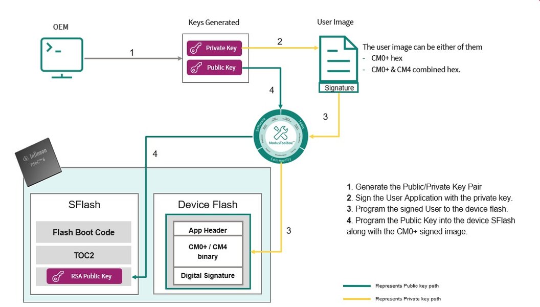
1. Generate Cryptographic Keys and Signing Certificates
Secure boot relies on asymmetric cryptography to verify firmware authenticity. You will need to generate a pair of cryptographic keys: a private key for signing your firmware and a public key that will be programmed onto the device for verification.
- Use tools like OpenSSL or scripts provided within the CySecureTools package to generate RSA or ECC key pairs.
- These keys are fundamental to the secure boot process, as the device's bootloader will use the public key to validate the digital signature of any incoming firmware.
2. Create and Configure Security Policies
Security policies define the rules and restrictions governing your device's secure boot behavior. This is typically done using the "Secure Policy" Configurator.
- Open the Secure Policy Configurator (part of ModusToolbox™ Edge Protect Security Suite).
- Define various security parameters, including:
- Flash memory partitions: Segmenting memory for secure and non-secure code.
- Debug port access restrictions: Preventing unauthorized debugging or code extraction.
- Lifecycle state (LCS) policies: Managing different device states (e.g., development, production).
- Rollback protection: Configuring the rollback counter to prevent flashing older, vulnerable firmware versions.
- Application format and address: Specifying parameters like
TOC2_FIRST_USER_APP_ADDRandTOC2_FIRST_USER_APP_FORMAT(e.g.,SI_APP_FORMAT) that the bootloader uses for verification.
- Save the generated policy file, which will guide the device's secure bootloader.
3. Provision the Device
Device provisioning is the process of securely injecting the generated public keys, certificates, and the defined security policies into the device's secure storage (e.g., eFuse or secure flash).
- Connect your PSoC 6 development kit to your host PC via the KitProg3 USB interface.
- Utilize CySecureTools commands or integrated ModusToolbox actions to:
- Program the public key into the device's secure storage.
- Load the security policy configuration.
- Program the secure bootloader (if not already present).
- This step establishes the Root of Trust on the hardware level, enabling secure boot validation.
4. Build and Sign the Application Firmware
Once the device is provisioned, your application firmware must be built and cryptographically signed before it can be executed on the PSoC 6.
- Develop your application within ModusToolbox.
- Configure your project's build settings to include post-build signing scripts. These scripts typically:
- Format the binary into the required TOC2 image format.
- Sign the application image using the private key generated in step 1.
- For devices in a specific Secure Lifecycle State (Secure LCS), the image must be signed with the same key used during provisioning.
- The image may also need to be shifted (e.g., by
0x2000 0000) for devices inNORMAL_NO_SECURELCS.
- The ModusToolbox Edge Protect Security Suite can assist in adding these post-build signing steps.
5. Program the Device and Test Secure Boot
After your firmware is built and signed, it can be programmed onto the PSoC 6 device. The secure boot process will then activate on reset.
- Use ModusToolbox IDE or Cypress Programmer to program the signed application to your device.
- On reset, the internal ROM bootloader on the Cortex-M0+ core reads the TOC2, locates your application, and verifies its digital signature using the preloaded public key.
- If verification is successful, control is handed over to your application (typically on the Cortex-M4 core).
- If the signature verification fails (e.g., due to tampering or an unsigned image), the boot process is halted, preventing the execution of untrusted code.
- Test the secure boot functionality by attempting to load unsigned or intentionally corrupted firmware to ensure it is rejected.
Deep Dive: The Importance of Secure Boot
Protecting Embedded Systems from Firmware Attacks
Secure Boot is more than just a configuration option; it's a foundational security mechanism for embedded systems. Its importance cannot be overstated in an era of increasing cyber threats targeting IoT devices and critical infrastructure.
The following video provides an excellent introduction to secure boot processes, explaining its value and function in protecting devices from malicious software. While it may not be PSoC 6 specific, the concepts discussed are universally applicable to embedded secure boot.
Microchip Principal Engineer Gerry Vahe introduces the Secure Boot process and discusses its value and function.
This video clarifies how secure boot forms a critical barrier against boot malware and unauthorized firmware. For PSoC 6, this translates to:
- Firmware Integrity: Ensures that the firmware has not been altered since it was signed by the legitimate developer. Any byte change will result in a signature mismatch, preventing execution.
- Firmware Authenticity: Guarantees that the firmware originates from a trusted source. Only code signed with the correct private key (corresponding to the public key stored on the device) will boot.
- Intellectual Property Protection: Prevents reverse engineering or cloning by unauthorized parties, as unsigned firmware cannot run.
- Protection Against Downgrades: Features like rollback counters stop attackers from reverting to older firmware versions that might contain known vulnerabilities.
- Secure Updates (DFU): When combined with secure boot, Device Firmware Update (DFU) mechanisms can ensure that over-the-air updates are also authenticated and verified before installation.
Additional Security Considerations and Best Practices
Enhancing Device Security Beyond Boot-Up
While secure boot is paramount, a comprehensive security strategy for PSoC 6 devices extends beyond the initial boot phase. Several other features and practices within ModusToolbox can further harden your embedded system.
Shared Memory Protection Unit (SMPU)
The SMPU is a hardware feature that allows for fine-grained access control to memory regions. It is crucial for isolating the two CPU cores (Cortex-M0+ and Cortex-M4) and protecting secure resources from non-secure applications. By configuring SMPU, you can:
- Prevent unauthorized access to sensitive data or code residing in secure memory regions.
- Isolate critical secure functions from potential vulnerabilities in the main application.
Debug Port Access Restrictions
Debug ports (like JTAG/SWD) are powerful interfaces that, if left unsecured, can be exploited to extract firmware, inject malicious code, or alter device behavior. Secure policies allow you to:
- Restrict or disable debug access based on the device's lifecycle state (e.g., completely disable in production).
- Require authentication or specific debug probe capabilities for access, preventing unauthorized debugging.
Chain of Trust (CoT) Implementation
A true Chain of Trust extends the security verification beyond the initial bootloader to every subsequent stage of firmware. For PSoC 6, this means:
- The ROM boot code verifies the primary bootloader.
- The primary bootloader then verifies the user application (and potentially a secondary bootloader).
- Each verified component then becomes a trusted base for the next stage, creating an unbroken chain of verified software.
Secure Firmware Updates (DFU)
For field-deployable devices, secure firmware updates are essential. Integrating DFU with secure boot ensures that any updates applied are also cryptographically signed and verified, preventing malicious updates. ModusToolbox examples often include DFU support over interfaces like UART, demonstrating this capability.
Lifecycle State Management
PSoC 6 devices support different Lifecycle States (LCS), such as NORMAL_NO_SECURE (development) and Secure LCS (production). These states influence debug access, provisioning requirements, and boot behavior. It is critical to manage these transitions carefully:
- Provisioning typically occurs when transitioning to a secure LCS.
- The signing keys and policies must align with the device's current LCS.
Here's a comparison of various security considerations when implementing secure boot:
| Security Aspect | Description | Benefit in PSoC 6 Secure Boot |
|---|---|---|
| Cryptographic Keys | RSA/ECC key pairs for signing and verification. | Ensures firmware authenticity and integrity. |
| Secure Policy Configurator | Tool to define security rules (e.g., debug access, memory partitions). | Customizes and enforces device-specific security posture. |
| Device Provisioning | Injecting keys and policies into secure hardware. | Establishes hardware-bound Root of Trust. |
| Rollback Protection | Counter to prevent downgrading to older firmware. | Mitigates attacks exploiting known vulnerabilities in old versions. |
| Shared Memory Protection Unit (SMPU) | Hardware unit for memory access control. | Isolates secure code/data, prevents unauthorized access between cores. |
| Chain of Trust (CoT) | Sequential verification of boot stages. | Guarantees integrity of entire software stack from ROM to application. |
| Secure Firmware Updates (DFU) | Mechanisms for authenticated and verified over-the-air updates. | Ensures integrity of updates, preventing malicious code injection. |
| Debug Port Restrictions | Controlling access to debug interfaces. | Prevents unauthorized access for reverse engineering or code extraction. |
Visualizing Secure Boot Capabilities
A Radar Chart of PSoC 6 Security Features
To better understand the strengths of PSoC 6 in implementing secure boot, let's visualize its capabilities across various dimensions critical for robust embedded security.
This radar chart illustrates how PSoC 6 capabilities align with general industry best practices for secure boot. It shows strong performance in key areas such as cryptographic signing, hardware root of trust, and chain of trust expansion, demonstrating the robust nature of its secure boot implementation within ModusToolbox.
Mindmap: Key Components of PSoC 6 Secure Boot
Mapping the Interconnected Elements for a Secure System
This mindmap visually represents the core components and processes involved in configuring secure boot on PSoC 6 using ModusToolbox. It highlights the relationships between the tools, phases, and security features.
This mindmap provides a structured overview, illustrating how each component and step interlinks to form a comprehensive secure boot solution for PSoC 6 microcontrollers.
Frequently Asked Questions (FAQ)
Conclusion
Configuring secure boot on PSoC 6 ModusToolbox is a critical step towards building robust and trustworthy embedded systems. By leveraging the dual-core architecture, immutable ROM boot code, and comprehensive toolchain provided by Infineon, developers can establish a strong Chain of Trust from the very first instruction executed. The process, while multifaceted, is well-supported by ModusToolbox's integrated tools like the Secure Policy Configurator and CySecureTools, which streamline key generation, policy definition, device provisioning, and automated firmware signing.
Beyond the core secure boot mechanism, implementing additional security considerations such as Shared Memory Protection Units (SMPU), debug port restrictions, and secure firmware update mechanisms further enhances the overall security posture. By diligently following these steps and understanding the underlying security principles, developers can ensure their PSoC 6-based applications are resilient against unauthorized access, tampering, and intellectual property theft, paving the way for truly secure IoT and embedded solutions.
Recommended Further Exploration
- How to implement Chain of Trust on PSoC 6 MCUs?
- Best practices for secure firmware updates on embedded systems?
- Understanding PSoC 6 lifecycle states and security implications?
- Advanced features of ModusToolbox Edge Protect Security Suite?