
Unlocking the Secrets of a Darkness Detector Circuit
Discover how to create a simple yet effective circuit using light-sensing components
Key Insights
- Component Functionality: Understand the roles of the LDR, transistor, resistors, and other components in detecting ambient light.
- Circuit Configuration: Learn how to arrange components into a voltage divider and switching circuit to trigger an output when darkness sets in.
- Practical Applications: Explore real-world applications such as automated lighting, security systems, and alarm systems.
Comprehensive Darkness Detector Setup
The darkness detector circuit is a reliable, cost-effective method of automatically activating a device when ambient light levels fall below a predetermined threshold. Its foundation lies in using a light-sensitive resistor, commonly known as an LDR (Light Dependent Resistor), which exhibits a significant change in resistance depending on the intensity of the light. When incorporated into a circuit, the LDR works in tandem with other components such as transistors, resistors, and power supplies to switch on an output device (for instance, an LED, buzzer, or relay) when it detects darkness.
Component Breakdown
Before you begin assembling the circuit, it is essential to understand each component's role:
Light Dependent Resistor (LDR)
The LDR is the primary sensor in the circuit. Its resistance is inversely proportional to the light intensity hitting it. Under bright conditions, the LDR exhibits low resistance, whereas in dim light or darkness, its resistance increases significantly. This property is utilized to detect changes in ambient light.
Transistor (e.g., BC547 or NPN)
The transistor acts as an electronic switch that controls the flow of current to the output device. When the LDR senses darkness, its increased resistance leads to a voltage change which is amplified by the transistor, thus activating the device connected to the collector.
Resistors and Voltage Divider
Resistors are critical for setting the correct biasing of the transistor. In this circuit, a fixed resistor (commonly 10kΩ to 50kΩ) is paired with the LDR in a voltage divider format. The voltage divider arrangement ensures that the voltage at the transistor's base changes with ambient light, effectively toggling the transistor’s operation.
555 Timer (Optional Integration)
In some advanced configurations, a 555 timer IC can be used in astable mode to generate continuous pulses, providing enhanced control over the output device’s activation. This configuration is especially useful for applications that require a delay or periodic activation when darkness is detected.
Output Devices
The final component in the circuit is the output device, which can be an LED, buzzer, or even a relay that controls a larger lighting system. The output device is activated when the transistor conducts, signaling detected darkness.
Circuit Design and Construction
The following sections will guide you through the assembly of your darkness detector circuit.
Step 1: Assembling the Components
Gather the following essential components:
| Component | Description | Typical Value |
|---|---|---|
| LDR | Light Dependent Resistor | - |
| Transistor | BC547 or similar NPN transistor | - |
| Resistor 1 | Resistor for voltage divider | 10kΩ to 50kΩ |
| Resistor 2 | Current limiting resistor for output device | 1kΩ (if using an LED) |
| Power Supply | Battery | 9V recommended |
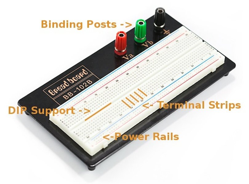
| Breadboard and Jumper Wires | For prototyping connections | - |
This table provides a quick reference to the components you will need, ensuring that your circuit assembly process is organized and efficient.
Step 2: Wiring the Circuit
The circuit is constructed by connecting the LDR and resistor in series, forming a voltage divider. The junction between these two components is linked to the base of the transistor. In darkness, the voltage at this junction rises due to the high resistance of the LDR, turning on the transistor. Below is a simplified schematic explanation:
- Connect the positive terminal of your battery to one end of the fixed resistor.
- Join the other end of the resistor to one terminal of the LDR, forming the voltage divider.
- Connect the joint node from the resistor and LDR to the base of the transistor.
- Attach the LDR’s other terminal to the ground.
- Link the transistor’s emitter directly to the ground.
- Connect the output device (LED) to the battery’s positive terminal through a current-limiting resistor, and then attach its other lead to the collector of the transistor.
When ambient light is abundant, the LDR’s lower resistance ensures that the base voltage remains low, keeping the transistor off. In contrast, when it gets dark, the increased resistance raises the base voltage, allowing the transistor to conduct and activate the LED or any other connected device.
Step 3: Testing and Calibration
After assembling the circuit on a breadboard, perform the following tests:
- Expose the LDR to bright light. Ensure that the LED remains off (or the output device is inactive) as the transistor should not conduct under high illumination.
- Place the circuit in a dark environment and observe the activation of the LED or device. Adjust the resistor value if the sensitivity needs fine-tuning.
- Optionally, incorporate a potentiometer in place of the fixed resistor to allow ongoing adjustments for different lighting conditions.
This calibration ensures that your detector can accurately differentiate between day and night conditions, minimizing false activations due to ambient light variations.
Visual Representations
To further enhance your understanding, the following visual elements illustrate the circuit behavior and design.
Radar Chart: Component Efficacy Comparison
The radar chart below visualizes our opinions regarding the roles and performances of key components within the darkness detector circuit. The chart includes subjective ratings based on design efficiency, sensitivity, ease of calibration, and versatility.
Mermaid Mindmap Diagram: Circuit Overview
This Mermaid.js mindmap provides a structured overview of the key components and the workflow in a darkness detector circuit, summarizing the interconnections and operational flow.
Advanced Configuration Using the 555 Timer IC
For those seeking further sophistication in your darkness detector project, consider integrating a 555 timer IC into your design. The 555 timer can be used in an astable configuration to generate continuous pulses when darkness is sensed. This method offers the possibility of adding a delay, creating blinking patterns for the output device, or even interfacing with other digital circuits.
In such a configuration, the LDR sensor continues to form a voltage divider, but its output now controls the reset or trigger pin of the 555 timer. When darkness is detected, the 555 timer begins to oscillate, and its output can be harnessed to drive larger loads, such as relays to control home lighting systems. Experimenting with various resistor and capacitor values allows you to adjust the oscillation frequency and achieve the desired operational behavior.
Practical Applications and Customization
This darkness detector circuit is a versatile project with multiple real-world applications:
- Automated Street and Garden Lighting: Use the circuit to trigger outdoor lighting systems automatically when dusk falls.
- Security and Alarm Systems: Integrate with alarm circuits that become active in low-light conditions, thus enhancing security during the night.
- Smart Home Integration: Connect the circuit with home automation systems to control various devices based on ambient lighting.
- Portable Nightlights: Create small, battery-powered nightlights that activate when it gets dark, making them ideal for bedrooms or corridors.
- Educational and DIY Projects: Serve as an excellent introduction to basic electronics, sensor integration, and circuit design.
By customizing the resistor values and incorporating potentiometers, you can tailor the sensitivity of your detector to suit particular environments, ensuring reliable performance under varying light conditions.
FAQ Section
Additional Learning Resources
For those interested in further expanding their knowledge, the following resources offer a more in-depth look at darkness detector circuits and related electronics projects:
- How to Make LDR Darkness Sensor Circuit - Instructables
- Light Sensor and Darkness Detector Circuit - Elonics
- LDR Darkness Sensor Circuit - Electric DIY Lab
- Building a Simple Darkness Detector Using LDR - Instructables
- Dark Detector with 555 Timer - Compile IOT
Recommended Related Queries
Last updated April 1, 2025