
Unlock the Blueprint: Designing Your Robust Device Management & Tracking System
A comprehensive guide to structuring Chapter Four of your project, integrating systems, architecture, database, program, and interface design.
Embarking on the design phase of your Device Management and Tracking System project is a critical step. This chapter lays the foundation for a successful web application that not only efficiently manages electronic devices but also prioritizes robust security through Role-Based Access Control (RBAC) and data encryption. Let's delve into the specific components required for Chapter Four.
Key Design Considerations
Essential Insights for Your Project
- Visual Clarity with UML: Employing diagrams like Context, DFD, and Activity diagrams provides a clear, shared understanding of the system's scope, data flow, and operational workflows, crucial for development teams.
- Layered Security Integration: Embedding security measures like RBAC and encryption from the architectural and database design phases ensures data protection is fundamental, not an afterthought.
- User-Centric Interface: Designing an intuitive web application interface is paramount for efficient device registration, management, and tracking, tailored to different user roles.
1. Systems Diagrams: Visualizing the Flow
Understanding Interactions and Processes
Systems diagrams are indispensable tools for illustrating how your Device Management and Tracking System (DMTS) operates, interacts with users and other systems, and processes data. They provide a high-level blueprint essential for aligning development efforts.
UML Context Diagrams: Defining the Boundaries
A Context Diagram offers the broadest view of your system. It depicts the DMTS as a central entity and highlights its interactions with external actors and systems. This diagram clarifies the project's scope from the outset.
- Central System: Your Web Application (DMTS).
- External Entities/Actors:
- Device Users (Employees, individuals registering devices)
- Administrators (Managing users, roles, devices, security settings)
- Potentially, external authentication services or APIs
- The Devices themselves (sending tracking data)
- Interactions: Data flows like device registration requests, user login credentials, tracking data uploads, configuration commands, generated reports, and security policy enforcement.
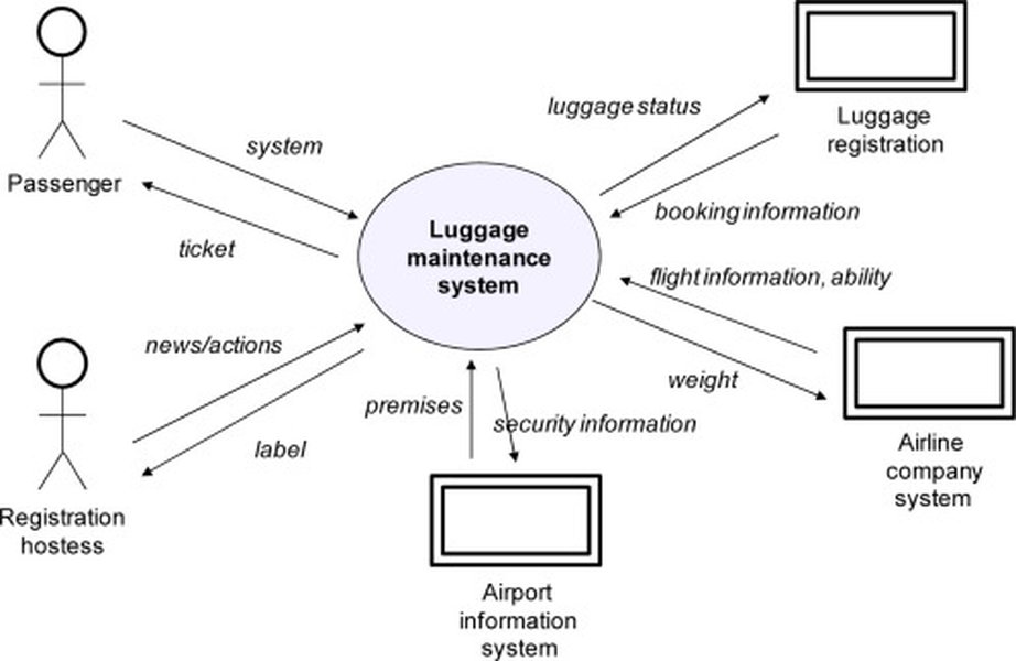
Illustrative example showing system context and external interactions.
Data Flow Diagrams (DFD): Tracing the Data
DFDs break down how data moves through the DMTS. They are vital for understanding the processing involved in device registration, user synchronization, tracking updates, and security enforcement.
- Level 0 DFD: Shows the main processes like 'Register Device', 'Manage Users', 'Track Device Location', 'Apply Security Policies', interacting with data stores (e.g., 'Device Database', 'User Database') and external entities.
- Level 1+ DFDs: Provide more detail for each major process. For 'Register Device', this might include sub-processes like 'Validate Input Data', 'Check User Permissions (RBAC)', 'Encrypt Device Details', 'Store Registration Info', 'Link Device to User'.
- Data Stores: Represent where data resides (e.g., Device Registry, User Profiles, Audit Logs).
- Data Flows: Show the data being transferred (e.g., 'Device Specs', 'User Credentials', 'Location Coordinates', 'Role Permissions').
Activity Diagrams: Mapping the Workflow
Activity diagrams model the sequence of actions within specific processes, including decisions and parallel activities. They are excellent for visualizing complex workflows like device onboarding, user authentication with RBAC checks, or handling tracking data updates.
- Example Workflow (Device Registration): Start -> User Logs In -> Authenticate User -> Check Role for Registration Permission (RBAC Decision Point) -> [If Permitted] Display Registration Form -> User Submits Details -> Validate Data -> Encrypt Sensitive Data -> Store Device Info in Database -> Link Device to User Account -> Generate Confirmation -> End. [If Not Permitted] Show Access Denied Message -> End.
- These diagrams clearly illustrate how security measures like RBAC are integrated into the system's operational flow.
2. Architectural Design: The System's Foundation
Structuring Hardware and Network Infrastructure
The architectural design outlines the physical and network components supporting your web application. A well-defined architecture ensures scalability, reliability, and security – crucial for managing potentially numerous devices and sensitive data.
Hardware Considerations
Specify the hardware needed to run the DMTS effectively.
- Servers: Detail the requirements for web servers (hosting the application), application servers (handling business logic), and database servers. Consider cloud-based solutions (e.g., AWS, Azure) for scalability and managed infrastructure.
- Processing Power & Storage: Estimate needs based on the expected number of devices, users, data volume (especially tracking logs), and processing overhead for encryption/decryption.
- Device Hardware: While the system manages electronic devices, consider if any specific hardware is part of the *tracking* infrastructure itself (e.g., dedicated IoT gateways or sensors if applicable).
Networking Infrastructure
Define the network topology and protocols for secure and efficient communication.
- Client-Server Model: Users access the web application via browsers. Devices communicate data back to the server(s).
- Communication Protocols: Use secure protocols like HTTPS for web traffic. For device communication (especially tracking data), consider MQTT over TLS or secure WebSockets for efficiency and real-time updates, ensuring data is encrypted in transit.
- Network Security: Implement firewalls to protect servers. Consider VPNs for secure administrative access. Network segmentation might be used to isolate different parts of the system based on security requirements (supporting RBAC at the network level).
- Scalability & Reliability: Plan for load balancing across servers and potentially database replication or clustering to handle growth and ensure high availability.
3. Database Design: Organizing the Data
Structuring Information with ER Diagrams and Normalization
The database is the heart of your DMTS, storing critical information about devices, users, roles, and tracking history. A well-designed database ensures data integrity, efficiency, and security.
Entity-Relationship (ER) Diagrams
ER diagrams visually model the structure of your database, defining the entities (tables), their attributes (columns), and the relationships between them.
- Key Entities:
Users(UserID, Name, Email, PasswordHash, RoleID)Roles(RoleID, RoleName, Description)Permissions(PermissionID, PermissionName)RolePermissions(RoleID, PermissionID) - Manages RBACDevices(DeviceID, DeviceName, DeviceType, SerialNumber, Status, OwnerUserID, RegistrationDate)DeviceTracking(TrackingID, DeviceID, Latitude, Longitude, Timestamp)AuditLogs(LogID, UserID, Action, Timestamp, Details)
- Relationships: Define connections like one-to-many (e.g., one User can own multiple Devices) and many-to-many (e.g., Roles to Permissions). Use primary keys (PK) and foreign keys (FK) to link tables.
Normalized Databases
Normalization is the process of organizing database tables to minimize data redundancy and improve data integrity. Aim for at least the Third Normal Form (3NF).
- Benefits: Reduces storage space, prevents data inconsistencies (e.g., updating a user's role in only one place), simplifies data management, and enhances security by structuring data logically.
- Example: Instead of storing role names directly in the Users table, use a RoleID foreign key linking to a separate Roles table. This ensures consistency and makes managing roles (and thus RBAC) much easier. Sensitive data fields (like passwords or potentially certain device identifiers) should be stored encrypted within the database.
4. Program Design: Building the Logic
Defining Software Components and Interactions
Program design translates the system requirements and architectural choices into a blueprint for the actual software code. It details the classes, their interactions, code organization, and core algorithms.
Class Diagrams
Class diagrams depict the static structure of your object-oriented system. They show the classes, their attributes (data), methods (operations), and relationships (like inheritance, association).
- Example Classes:
User,Device,Role,Permission,Location,RegistrationService,TrackingService,AuthenticationManager,AuthorizationManager(for RBAC),EncryptionUtil. - Define attributes (e.g.,
Deviceclass hasdeviceName,status) and methods (e.g.,Deviceclass hasregister(),updateStatus(),getLocation()). - Show relationships: A
User'owns' multipleDeviceobjects. AnAuthenticationManager'uses' theUserclass.
Sequence Diagrams
Sequence diagrams illustrate how objects interact over time to perform a specific task or scenario. They are excellent for detailing the logic flow for key functionalities.
- Example Scenario (User Login & View Devices):
1. User enters credentials in UI.
2. UI sends login request to
AuthenticationManager. 3.AuthenticationManagerretrieves user data (potentially fromUserDAO/Repository). 4.AuthenticationManagerverifies credentials. 5. Upon success, fetches user role viaAuthorizationManager. 6. UI requests device list fromDeviceService. 7.DeviceServicechecks user permissions (RBAC) viaAuthorizationManager. 8. If authorized,DeviceServiceretrieves devices (fromDeviceDAO) associated with the user. 9.DeviceServicereturns the device list to the UI. 10. UI displays the devices. - These clearly show how components collaborate, including security checks.
Package Diagrams
Package diagrams help organize your codebase into logical groups or modules, managing complexity in larger projects.
- Example Packages:
com.yourcompany.dmts.controller(Handles web requests)com.yourcompany.dmts.service(Contains business logic)com.yourcompany.dmts.model(Data entities/domain objects)com.yourcompany.dmts.repository(Data access layer)com.yourcompany.dmts.security(Authentication, RBAC, Encryption)com.yourcompany.dmts.util(Utility classes)
Pseudocode
Pseudocode provides an informal, high-level description of algorithms before writing actual code. It clarifies complex logic.
- Example (RBAC Check):
FUNCTION hasPermission(userID, requiredPermission): userRole = getUserRole(userID) rolePermissions = getPermissionsForRole(userRole) IF requiredPermission IS IN rolePermissions THEN RETURN TRUE ELSE RETURN FALSE ENDIF ENDFUNCTION - Example (Data Encryption on Save):
PROCEDURE saveDeviceDetails(deviceData):
  sensitiveField = deviceData.getSensitiveInfo()
  encryptedField = encryptData(sensitiveField, encryptionKey)
  deviceData.setSensitiveInfo(encryptedField)
  saveToDatabase(deviceData)
ENDPROCEDURE
Design Aspects Complexity Radar
Relative Importance and Complexity in Your DMTS Project
This chart visualizes the estimated importance and complexity of various design facets for your specific Device Management and Tracking System, considering the emphasis on security (RBAC, Encryption) and a unified web application. Higher values indicate greater focus or complexity required.
Mindmap of Design Chapter Structure
Visualizing the Components of Chapter Four
This mindmap provides a hierarchical overview of the key sections and sub-sections discussed within the Design chapter of your project documentation.
Device Management & Tracking System"] id1["1. Systems Diagrams"] id1a["Context Diagram
(Scope & Actors)"] id1b["Data Flow Diagrams (DFD)
(Data Movement)"] id1c["Activity Diagrams
(Workflows)"] id2["2. Architectural Design"] id2a["Hardware
(Servers, Cloud, Storage)"] id2b["Networking
(Protocols, Security, Topology)"] id3["3. Database Design"] id3a["ER Diagrams
(Entities & Relationships)"] id3b["Normalization
(Integrity & Efficiency, 3NF)"] id3c["Security
(Encryption at Rest)"] id4["4. Program Design"] id4a["Class Diagrams
(OOP Structure)"] id4b["Sequence Diagrams
(Interactions)"] id4c["Package Diagrams
(Modularity)"] id4d["Pseudocode
(Algorithm Logic)"] id4e["Security Implementation
(RBAC Logic, Encryption)"] id5["5. Interface Design (UI/UX)"] id5a["Web Application Screens
(Login, Dashboard, Registration)"] id5b["User Roles View
(RBAC reflected in UI)"] id5c["Wireframes / Mockups"] id5d["Usability & Accessibility"]
5. Interface Design: The User's View
Crafting the Web Application Interface
The interface design focuses on how users will interact with your DMTS web application. A well-designed UI is intuitive, efficient, and caters to the needs of different user roles (as defined by RBAC).
Key Interface Components
- Login/Authentication Screen: Secure entry point.
- Dashboard: Provides an overview of managed devices, potentially customizable based on user role. Shows device status, recent activity, alerts.
- Device Registration Form: Clear and easy-to-use form for capturing necessary device details (type, serial number, owner assignment, etc.).
- Device List/Management View: Allows viewing, searching, filtering, and managing registered devices. Details displayed might vary based on RBAC permissions.
- Tracking View: If real-time tracking is a feature, this could be a map-based view or a list showing current/last known locations and status.
- User Management (Admin): Interface for administrators to add/edit users and assign roles (RBAC management).
- Role/Permission Management (Admin): Interface to define roles and their associated permissions.
- Reporting Interface: Allows generating reports on device inventory, activity, or compliance.
Visual Design and Mockups
While actual screenshots come later, this section should include wireframes or mockups (low or high fidelity) illustrating the layout, navigation, and key elements of the UI. These visuals help communicate the intended user experience and ensure the design meets project objectives, including clearly presenting device/user information and reflecting security constraints.
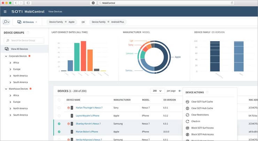
Example of a Mobile Device Management (MDM) dashboard, illustrating potential UI elements like device lists, status indicators, and management options.
Summary Table: Design Artifacts
Purpose and Relevance of Key Design Elements
This table summarizes the primary design artifacts discussed, their purpose, and their specific relevance to achieving your project objectives of creating a secure, unified web application for device management and tracking.
| Design Artifact | Purpose | Relevance to Project Objectives (Web App, RBAC, Encryption) |
|---|---|---|
| Context Diagram | Define system scope and external interactions. | Establishes boundaries for the web application and identifies actors interacting with it. |
| Data Flow Diagram (DFD) | Illustrate how data moves through the system. | Shows flow for device registration, user sync, tracking data, and where security processes (RBAC checks, encryption points) occur. |
| Activity Diagram | Model workflows and process steps. | Details steps for user actions within the web app, explicitly showing decision points for RBAC and process flows involving encryption. |
| ER Diagram | Model database structure and relationships. | Defines how device, user, and role/permission data (for RBAC) are stored and linked. Foundation for data encryption storage. |
| Normalized Database Schema | Ensure data integrity, reduce redundancy, improve efficiency. | Crucial for reliable user/device synchronization and securely organizing data for RBAC and encrypted storage. |
| Class Diagram | Define software classes, attributes, methods, relationships. | Structures the code for the web application, including classes for handling devices, users, RBAC logic, and encryption utilities. |
| Sequence Diagram | Show object interactions over time for specific scenarios. | Illustrates dynamic behavior, like how RBAC checks are performed during a user request or how data is encrypted before saving. |
| UI Mockups/Wireframes | Visualize the user interface and user experience. | Designs the web application's look and feel, ensuring usability and showing how RBAC restricts views/actions for different users. |
Relevant Insights on Mobile Device Management (MDM)
Understanding Core Concepts
Mobile Device Management (MDM) shares many principles with your project. MDM systems are designed to administer and secure mobile devices like smartphones and tablets within an organization. Understanding MDM concepts can provide valuable insights into device enrollment, policy enforcement, security configurations, and application management, many of which are applicable to your broader electronic device management system. The video below offers a concise overview of MDM.
This video explains what MDM is, how it works through administration consoles and device agents/profiles, and its importance in securing corporate data on mobile endpoints. Key takeaways include the centralized management capabilities, policy enforcement, and integration potential with broader IT systems, mirroring the goals of your own DMTS.
Frequently Asked Questions (FAQ)
Clarifying Key Design Concepts
Why are UML diagrams crucial for this project?
How does Role-Based Access Control (RBAC) influence the database and program design?
What are the primary considerations for network security in a device tracking system?
Why is database normalization important here?
What makes a good user interface for device management?
Recommended Next Steps
Explore Further Insights
- Explore best practices for implementing Role-Based Access Control in modern web applications.
- Investigate secure database schemas suitable for storing sensitive device tracking information.
- Learn about scalable cloud architecture patterns for high-volume device management systems.
- Compare communication protocols like MQTT and HTTPS for real-time device data transmission.
References
Supporting Resources

Last updated May 1, 2025