
Mastering ESP32-CAM to Arduino Data Communication: A Complete Integration Guide
Transform your projects by harnessing camera data from ESP32-CAM to power intelligent Arduino applications
Key Insights for ESP32-CAM to Arduino Communication
- Serial communication (UART) provides the most straightforward method for connecting ESP32-CAM to Arduino boards
- Data processing strategies are crucial due to Arduino's limited memory compared to image data size
- Voltage level considerations between ESP32's 3.3V and Arduino's 5V require proper electrical interfacing
Integrating an ESP32-CAM with an Arduino board opens up numerous possibilities for intelligent projects combining visual data with Arduino's processing capabilities. While this setup presents some challenges, particularly with data size and communication protocols, the following comprehensive guide will walk you through establishing reliable communication and data flow between these devices.
Hardware Setup and Connections
Before diving into the code, proper hardware connections are critical for successful communication between your ESP32-CAM and Arduino board.
Essential Hardware Components
- ESP32-CAM module
- Arduino board (Uno, Mega, Nano, etc.)
- FTDI programmer (for programming the ESP32-CAM)
- Jumper wires
- Breadboard
- Logic level converter (recommended)
- Power supply (5V for both boards)
Connection Diagram for Serial Communication
The most reliable method for transmitting data between ESP32-CAM and Arduino is through serial (UART) communication:
| ESP32-CAM Pin | Arduino Pin | Description |
|---|---|---|
| VCC (5V) | 5V | Power supply |
| GND | GND | Common ground |
| U0T (GPIO1) | RX (Pin 0) | ESP32 TX to Arduino RX* |
| U0R (GPIO3) | TX (Pin 1) | ESP32 RX to Arduino TX* |
*Note: For the RX connection from ESP32-CAM to Arduino TX, a voltage divider or logic level converter is recommended since ESP32 operates at 3.3V while most Arduino boards operate at 5V.
Voltage Level Consideration
The ESP32-CAM operates at 3.3V logic levels, while Arduino (especially Arduino Uno) typically uses 5V logic. To prevent damage to the ESP32-CAM, implement one of the following solutions:
- Use a logic level converter between the boards
- Create a voltage divider using resistors (e.g., 2.2K and 3.3K resistors) for the Arduino TX to ESP32 RX line
- If using Arduino boards with 3.3V logic (like Arduino Due), direct connections are possible
Programming the ESP32-CAM
The ESP32-CAM needs to be programmed to capture image data and send it to the Arduino. Due to memory constraints on the Arduino, you'll typically need to process or reduce the data on the ESP32-CAM before transmission.
Setting Up the Arduino IDE for ESP32-CAM
- Install the ESP32 board manager in Arduino IDE
- Select the appropriate ESP32 board (ESP32 Wrover Module or AI Thinker ESP32-CAM)
- Set the appropriate partition scheme (Huge APP)
- Connect the ESP32-CAM to your computer using an FTDI programmer
ESP32-CAM Sample Code
#include "esp_camera.h"
#include "camera_pins.h"

// Define Serial communication pins
#define SERIAL_TX 1  // GPIO1
#define SERIAL_RX 3  // GPIO3

void setup() {
  // Start serial communication
  Serial.begin(115200);

  // Initialize camera
  camera_config_t config;
  config.ledc_channel = LEDC_CHANNEL_0;
  config.ledc_timer = LEDC_TIMER_0;
  config.pin_d0 = Y2_GPIO_NUM;
  config.pin_d1 = Y3_GPIO_NUM;
  config.pin_d2 = Y4_GPIO_NUM;
  config.pin_d3 = Y5_GPIO_NUM;
  config.pin_d4 = Y6_GPIO_NUM;
  config.pin_d5 = Y7_GPIO_NUM;
  config.pin_d6 = Y8_GPIO_NUM;
  config.pin_d7 = Y9_GPIO_NUM;
  config.pin_xclk = XCLK_GPIO_NUM;
  config.pin_pclk = PCLK_GPIO_NUM;
  config.pin_vsync = VSYNC_GPIO_NUM;
  config.pin_href = HREF_GPIO_NUM;
  config.pin_sscb_sda = SIOD_GPIO_NUM;
  config.pin_sscb_scl = SIOC_GPIO_NUM;
  config.pin_pwdn = PWDN_GPIO_NUM;
  config.pin_reset = RESET_GPIO_NUM;
  config.xclk_freq_hz = 20000000;
  config.pixel_format = PIXFORMAT_JPEG;

  // Configure image quality and size
  config.frame_size = FRAMESIZE_VGA;  // 640x480
  config.jpeg_quality = 10;  // 0-63, lower means higher quality
  config.fb_count = 2;

  // Initialize the camera
  esp_err_t err = esp_camera_init(&config);
  if (err != ESP_OK) {
    Serial.printf("Camera init failed with error 0x%x", err);
    return;
  }

  Serial.println("Camera initialized successfully");
}

void loop() {
  // Capture a frame
  camera_fb_t *fb = esp_camera_fb_get();
  if (!fb) {
    Serial.println("Camera capture failed");
    return;
  }

  // Process data before sending (example: image dimensions and center pixel value)
  uint16_t width = fb->width;
  uint16_t height = fb->height;
  uint32_t len = fb->len;

  // Send processed data to Arduino
  Serial.print("DATA:");
  Serial.print(width);
  Serial.print(",");
  Serial.print(height);
  Serial.print(",");
  Serial.println(len);

  // Option: Send a small amount of pixel data
  if (len > 100) {
    Serial.write(fb->buf, 100);  // Send first 100 bytes of image data
  }

  // Return the frame buffer
  esp_camera_fb_return(fb);

  delay(5000);  // Capture every 5 seconds
}
Data Processing Strategies
Rather than sending full images (which could be several hundred KB), consider these approaches:
- Extract metadata only (dimensions, average brightness)
- Detect features on the ESP32-CAM and send only results
- Convert to grayscale and downsample the image
- Implement edge detection or motion detection on ESP32-CAM and send only relevant pixels
- Send sections of the image sequentially with identifiers
Programming the Arduino Board
The Arduino board needs to be programmed to receive and process the data sent from the ESP32-CAM, allowing you to use it as variables in your project.
Arduino Sample Code
// Arduino code to receive data from ESP32-CAM

String receivedData = "";
boolean newData = false;
int imageWidth = 0;
int imageHeight = 0;
int dataLength = 0;
byte pixelData[100]; // Buffer for pixel data

void setup() {
  Serial.begin(115200); // Same baud rate as ESP32-CAM
  Serial.println("Arduino ready to receive data");
}

void loop() {
  // Read data from ESP32-CAM
  while (Serial.available() > 0) {
    char c = Serial.read();

    // Process text data
    if (c != '\n') {
      receivedData += c;
    } else {
      newData = true;
    }
  }

  // Process received data
  if (newData) {
    // Check if it's metadata
    if (receivedData.startsWith("DATA:")) {
      receivedData = receivedData.substring(5); // Remove "DATA:" prefix

      // Parse the data
      int firstComma = receivedData.indexOf(',');
      int secondComma = receivedData.indexOf(',', firstComma + 1);

      if (firstComma != -1 && secondComma != -1) {
        imageWidth = receivedData.substring(0, firstComma).toInt();
        imageHeight = receivedData.substring(firstComma + 1, secondComma).toInt();
        dataLength = receivedData.substring(secondComma + 1).toInt();

        // Display the metadata
        Serial.print("Image dimensions: ");
        Serial.print(imageWidth);
        Serial.print("x");
        Serial.println(imageHeight);
        Serial.print("Data length: ");
        Serial.println(dataLength);

        // Now ready to receive pixel data
        Serial.println("Ready for pixel data");
      }
    }

    // Clear for next data
    receivedData = "";
    newData = false;
  }

  // Read binary pixel data (if available and after metadata)
  if (imageWidth > 0 && Serial.available() > 0) {
    int bytesRead = Serial.readBytes(pixelData, min(100, Serial.available()));

    // Now you can use pixelData as a variable in your project
    // Example: Check first pixel for brightness
    if (bytesRead > 0) {
      Serial.print("First byte value: ");
      Serial.println(pixelData[0]);

      // Use the value for a project (example: control LED brightness)
      analogWrite(LED_BUILTIN, pixelData[0]);
    }
  }

  delay(100); // Short delay for stability
}
Using the Data in Arduino Projects
Once you've received and processed the data from ESP32-CAM, you can use it in various ways:
- Control outputs based on visual data (LEDs, motors, displays)
- Implement decision logic based on camera input
- Log data to SD card or send to another device
- Combine with other sensors for comprehensive environmental monitoring
- Create responsive installations that react to visual stimuli
Communication Methods: Capabilities Comparison
This chart compares different communication methods between ESP32-CAM and Arduino based on various factors including ease of implementation, data transfer speed, reliability, and complexity. Serial communication offers the best balance for beginners, while WiFi and SPI provide advantages in specific use cases.
Data Processing Workflow
Understanding the flow of data from capture to utilization is essential for implementing an effective ESP32-CAM to Arduino integration.
This mindmap illustrates the complete data flow process from capturing an image with the ESP32-CAM to utilizing the data in your Arduino project. Each step involves specific considerations and techniques to ensure efficient and reliable data transfer.
Visual Guide to ESP32-CAM and Arduino Connection
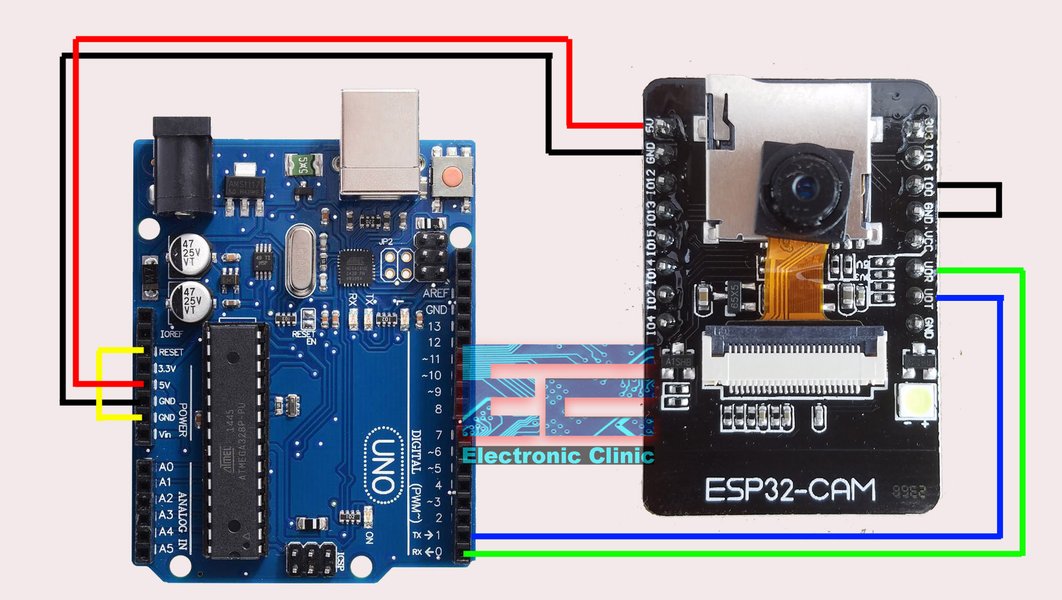
This connection diagram shows the proper wiring between an ESP32-CAM module and an Arduino board for programming and serial communication. The connections must be carefully made according to the pinout of both devices. For data collection, focus on the serial transmission pins (TX/RX) and ensure proper ground connections. When programming the ESP32-CAM, remember to connect GPIO0 to GND before powering on, then disconnect for normal operation.
Step-by-Step Implementation Example
In this section, we'll walk through a practical example of implementing ESP32-CAM to Arduino communication for a motion detection project.
This tutorial demonstrates how to program an ESP32-CAM using an Arduino UNO as a programmer, which is the first step in establishing communication between these devices. The video shows the hardware connections and setup process, providing a visual guide to complement the written instructions in this article.
Project Example: Motion Detection Light Controller
This example project uses the ESP32-CAM to detect motion and sends a signal to the Arduino to control lights.
ESP32-CAM Code
// ESP32-CAM Motion Detection Example
#include "esp_camera.h"
#include "camera_pins.h"

// Previous frame buffer for comparison
uint8_t *previous_frame = NULL;
size_t previous_len = 0;

// Motion detection threshold
#define MOTION_THRESHOLD 15
#define MOTION_PIXELS_PERCENT 5

void setup() {
  Serial.begin(115200);

  // Initialize camera (same as previous example)
  // ...camera configuration code...

  // Take initial reference frame
  camera_fb_t *fb = esp_camera_fb_get();
  if (fb) {
    previous_frame = (uint8_t*)malloc(fb->len);
    if (previous_frame) {
      memcpy(previous_frame, fb->buf, fb->len);
      previous_len = fb->len;
    }
    esp_camera_fb_return(fb);
  }
}

void loop() {
  // Capture new frame
  camera_fb_t *fb = esp_camera_fb_get();
  if (!fb) {
    Serial.println("Camera capture failed");
    return;
  }

  // Simple motion detection by comparing frames
  bool motion_detected = false;
  if (previous_frame && fb->len == previous_len) {
    int different_pixels = 0;

    // Simplified comparison - just check first 10000 bytes
    // For a real project, implement proper frame comparison
    for (int i = 0; i < min(10000, (int)fb->len); i++) {
      if (abs((int)fb->buf[i] - (int)previous_frame[i]) > MOTION_THRESHOLD) {
        different_pixels++;
      }
    }

    // Calculate percentage of different pixels
    float percent_different = (different_pixels * 100.0) / min(10000, (int)fb->len);

    // Determine if motion detected
    if (percent_different > MOTION_PIXELS_PERCENT) {
      motion_detected = true;
    }

    // Update previous frame
    memcpy(previous_frame, fb->buf, fb->len);
  }

  // Send result to Arduino
  if (motion_detected) {
    Serial.println("MOTION:1");
  } else {
    Serial.println("MOTION:0");
  }

  esp_camera_fb_return(fb);
  delay(500);  // Check for motion twice per second
}
Arduino Code
// Arduino Motion-Activated Light Controller
#define RELAY_PIN 7

String receivedData = "";
boolean newData = false;
bool motionDetected = false;

// Timer variables for light control
unsigned long lightOnTime = 0;
const unsigned long LIGHT_DURATION = 30000; // 30 seconds

void setup() {
  Serial.begin(115200);
  pinMode(RELAY_PIN, OUTPUT);
  digitalWrite(RELAY_PIN, LOW); // Start with light off
}

void loop() {
  // Read data from ESP32-CAM
  while (Serial.available() > 0) {
    char c = Serial.read();
    if (c != '\n') {
      receivedData += c;
    } else {
      newData = true;
    }
  }

  // Process received data
  if (newData) {
    if (receivedData.startsWith("MOTION:")) {
      String motionValue = receivedData.substring(7);

      // Convert to boolean
      if (motionValue == "1") {
        motionDetected = true;
        lightOnTime = millis();
        digitalWrite(RELAY_PIN, HIGH); // Turn light on
        Serial.println("Motion detected - Light ON");
      } else {
        motionDetected = false;
        // Don't turn off immediately - use timer
      }
    }

    receivedData = "";
    newData = false;
  }

  // Check if it's time to turn off the light
  if (motionDetected == false && (millis() - lightOnTime) > LIGHT_DURATION) {
    digitalWrite(RELAY_PIN, LOW); // Turn light off
  }
}
Frequently Asked Questions
References
- ESP32-CAM Post Image Photo to Server - Random Nerd Tutorials
- Send Photos Captured with the ESP32-CAM via Serial - Arduino Forum
- ESP32-CAM Serial Communication with Arduino Uno - Arduino Forum
- ESP32-CAM Programming Using Arduino, Issues Fixed - Electronic Clinic
- Getting Started with ESP32-CAM - Last Minute Engineers
- ESP32-CAM Object Detection - Eloquent Arduino
Recommended Searches
Last updated April 8, 2025