
Unlock Remote Vision: Connecting Your ESP32 Camera to the Arduino Cloud
A comprehensive guide to integrating your ESP32-CAM with Arduino's IoT platform for smart projects.
The ESP32-CAM is a powerful, low-cost microcontroller with an integrated camera and Wi-Fi, making it a popular choice for a variety of IoT projects, from home surveillance to remote monitoring. By connecting it to the Arduino Cloud, you can control your camera, manage data, and build interactive dashboards accessible from anywhere. This guide will walk you through the entire process, step by step.
Key Highlights
- Hardware & Software Prep: Learn to set up your ESP32-CAM with an FTDI programmer and configure your Arduino IDE with the necessary board packages and libraries.
- Arduino Cloud Integration: Discover how to add your ESP32-CAM as a device in the Arduino Cloud, create a "Thing," and manage cloud variables for communication.
- Camera Data Handling: Understand how to program your ESP32-CAM to capture images and send data or status updates to the Arduino Cloud, while being mindful of platform capabilities.
Understanding Your ESP32-CAM
Before diving into the connection process, it's essential to understand the ESP32-CAM module and its characteristics.
An ESP32-CAM module, showcasing its compact design with camera and Wi-Fi antenna.
Core Features
The ESP32-CAM typically features:
- An ESP32-S System-on-Chip (SoC) with dual-core processor.
- An integrated camera module, commonly the OV2640 (2-megapixel) or OV7670. The OV2640 is often preferred for its higher resolution and built-in JPEG encoding.
- Built-in Wi-Fi and Bluetooth capabilities.
- A microSD card slot for local storage (on many models).
Important Considerations
Power Requirements
The ESP32-CAM requires a stable 5V power supply. Insufficient power, especially when the camera or Wi-Fi is active, can lead to "brownout" errors and unexpected resets. Using the 5V pin for power is recommended over powering solely through some FTDI programmers. Ensure your power source can provide at least 2A, especially during Wi-Fi transmission or camera initialization.
Programming Interface
Most ESP32-CAM modules do not have a built-in USB-to-Serial converter. Therefore, you'll need an external FTDI (Future Technology Devices International) programmer or a similar USB-to-TTL serial adapter to upload code from your computer to the ESP32-CAM. This involves connecting the FTDI programmer's TX, RX, GND, and VCC pins to the corresponding pins on the ESP32-CAM.
Wi-Fi Connectivity
The ESP32-CAM supports 2.4GHz Wi-Fi, which is crucial for connecting to the Arduino Cloud.
Preparing Your Development Environment: Arduino IDE Setup
To program the ESP32-CAM, you need to configure the Arduino Integrated Development Environment (IDE).
1. Install Arduino IDE
If you haven't already, download and install the latest version of the Arduino IDE from the official website.
2. Add ESP32 Board Support
The Arduino IDE doesn't come with ESP32 support by default. You need to add it through the Boards Manager:
- Open Arduino IDE, go to File > Preferences (or Arduino IDE > Settings... on macOS).
- In the "Additional Boards Manager URLs" field, paste the following URL:
You can also addhttps://raw.githubusercontent.com/espressif/arduino-esp32/gh-pages/package_esp32_index.jsonhttps://dl.espressif.com/dl/package_esp32_index.jsonas an alternative or secondary URL. - Click "OK".
- Go to Tools > Board > Boards Manager....
- Search for "ESP32" and install the package by "Espressif Systems".
3. Select Board and Settings
Once the ESP32 package is installed:
- Go to Tools > Board > ESP32 Arduino and select "AI Thinker ESP32-CAM". If this specific option isn't available, "ESP32 Wrover Module" can often work as an alternative.
- Set Tools > Partition Scheme to "Huge APP (3MB No OTA/1MB SPIFFS)". This allocates more memory for your application code, which is beneficial for camera projects.
- Set Tools > Upload Speed to a high value like "921600" for faster uploads, though you might need to reduce it if you encounter upload issues.
- Select the correct COM port under Tools > Port once your FTDI programmer is connected to your computer and the ESP32-CAM.
Wiring the ESP32-CAM for Programming
Properly wiring your ESP32-CAM to the FTDI programmer is crucial for uploading code.
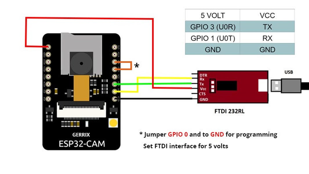
An example of wiring an FTDI programmer to an ESP32 module. Pinouts on your specific ESP32-CAM and FTDI programmer should be verified.
FTDI Connection Table
Here are the typical connections. Always double-check the pin labels on your specific ESP32-CAM and FTDI programmer.
| FTDI Pin | ESP32-CAM Pin | Purpose |
|---|---|---|
| 5V (or VCC) | 5V | Power Supply to ESP32-CAM |
| GND | GND | Common Ground |
| TXD (Transmit) | U0RXD (GPIO3) | Serial Data (FTDI sends, ESP32-CAM receives) |
| RXD (Receive) | U0TXD (GPIO1) | Serial Data (ESP32-CAM sends, FTDI receives) |
Entering Programming Mode
To enable code upload, the ESP32-CAM must be put into bootloader mode (also known as programming mode):
- Connect the GPIO0 pin on the ESP32-CAM to GND.
- After making this connection and ensuring all other wires are correctly in place, connect the FTDI programmer to your computer's USB port.
- Press the onboard reset (RST) button on the ESP32-CAM *while GPIO0 is connected to GND*. Some users find it sufficient to have GPIO0 connected to GND when powering up or initiating the upload.
- Once the code upload is complete, disconnect GPIO0 from GND and press the reset button again to run the new program in normal operation mode.
Configuring the Arduino Cloud
The Arduino Cloud allows you to manage your ESP32-CAM, define variables, and create dashboards.
1. Create an Arduino Cloud Account
If you don't have one, sign up for a free account on the Arduino Cloud website.
2. Add Your ESP32-CAM as a Device
- Log in to your Arduino Cloud account.
- Navigate to the "Devices" section.
- Click on "Add Device" or "Create Device".
- Select "Third Party Device" or "ESP32 device" (the interface may vary slightly). If asked for a specific board, you might choose a generic ESP32 option like "ESP32 Dev Module" or similar.
- Follow the prompts. You will be provided with a Device ID and a Secret Key. Crucial: Copy and save your Secret Key in a secure place immediately. It will not be shown again. This key is essential for your ESP32-CAM to authenticate with the Arduino Cloud.
3. Create a "Thing"
In Arduino Cloud terminology, a "Thing" represents your physical device and its associated cloud properties (variables).
- Go to the "Things" section and click "Create Thing".
- Link your newly added ESP32 device to this Thing.
- Add Variables: Define cloud variables that your ESP32-CAM will interact with. For example:
- A
booleanvariable namedcapture_image_trigger(Read & Write) to tell the camera to take a picture. - A
Stringvariable namedlast_image_status(Read Only) for the ESP32-CAM to report status like "Image captured" or "Upload failed". - If you intend to send small image data (like a Base64 encoded thumbnail), you might use a
Stringvariable, but be mindful of Arduino Cloud's variable size limits on free plans.
- A
- Configure network credentials (your Wi-Fi SSID and password) for the Thing. This information will be incorporated into the sketch.
Once your Thing is configured, the Arduino Cloud will automatically generate a skeleton sketch. This sketch includes the necessary libraries and code to connect to your Wi-Fi network and the Arduino Cloud, using the Device ID and Secret Key you saved earlier.
Programming the ESP32-CAM and Cloud Connection
Now, you'll modify the Arduino Cloud-generated sketch to include camera functionality and upload it to your ESP32-CAM.
1. Download and Modify the Sketch
- From your Thing's configuration page in Arduino Cloud, download the auto-generated sketch.
- Open this sketch in your Arduino IDE. It will contain placeholders for your Wi-Fi credentials and the Secret Key (if not already embedded). Ensure these are correctly filled in the
arduino_secrets.htab or directly in the main sketch file. - Integrate Camera Code: You need to add code to initialize the camera and handle image capture. The
esp_camera.hlibrary is essential for this. You can adapt code from the standard ESP32CameraWebServerexample (File > Examples > ESP32 > Camera > CameraWebServer) or use a more streamlined approach for just capturing and potentially sending data.
Example Code Structure
Below is a conceptual structure of what your ino file might look like, combining Arduino Cloud connectivity with basic camera initialization. Remember to define your camera pins correctly for the AI-Thinker model.
#include "thingProperties.h" // Generated by Arduino Cloud, includes secrets and cloud var declarations
#include <WiFi.h>
#include "esp_camera.h"

// Define camera model and pins (AI-THINKER model)
#define PWDN_GPIO_NUM     32
#define RESET_GPIO_NUM    -1 // -1 if not used
#define XCLK_GPIO_NUM      0
#define SIOD_GPIO_NUM     26
#define SIOC_GPIO_NUM     27

#define Y9_GPIO_NUM       35
#define Y8_GPIO_NUM       34
#define Y7_GPIO_NUM       39
#define Y6_GPIO_NUM       36
#define Y5_GPIO_NUM       21
#define Y4_GPIO_NUM       19
#define Y3_GPIO_NUM       18
#define Y2_GPIO_NUM        5
#define VSYNC_GPIO_NUM    25
#define HREF_GPIO_NUM     23
#define PCLK_GPIO_NUM     22

// Cloud variable linked in thingProperties.h, e.g.:
// bool capture_image_trigger;
// String last_image_status;
// void onCaptureImageTriggerChange(); // Callback function

void setup() {
  Serial.begin(115200);
  delay(1500); // Wait for serial monitor

  // Initialize camera
  camera_config_t config;
  config.ledc_channel = LEDC_CHANNEL_0;
  config.ledc_timer = LEDC_TIMER_0;
  config.pin_d0 = Y2_GPIO_NUM;
  config.pin_d1 = Y3_GPIO_NUM;
  config.pin_d2 = Y4_GPIO_NUM;
  config.pin_d3 = Y5_GPIO_NUM;
  config.pin_d4 = Y6_GPIO_NUM;
  config.pin_d5 = Y7_GPIO_NUM;
  config.pin_d6 = Y8_GPIO_NUM;
  config.pin_d7 = Y9_GPIO_NUM;
  config.pin_xclk = XCLK_GPIO_NUM;
  config.pin_pclk = PCLK_GPIO_NUM;
  config.pin_vsync = VSYNC_GPIO_NUM;
  config.pin_href = HREF_GPIO_NUM;
  config.pin_sccb_sda = SIOD_GPIO_NUM;
  config.pin_sccb_scl = SIOC_GPIO_NUM;
  config.pin_pwdn = PWDN_GPIO_NUM;
  config.pin_reset = RESET_GPIO_NUM;
  config.xclk_freq_hz = 20000000;
  config.pixel_format = PIXFORMAT_JPEG; // JPEG for smaller file size

  // Frame size (e.g., UXGA, SVGA, CIF) - smaller is better for cloud upload
  config.frame_size = FRAMESIZE_SVGA; // (800x600)
  config.jpeg_quality = 12; // 0-63, lower means higher quality
  config.fb_count = 1; // Use 1 frame buffer for simple capture, 2 for streaming

  esp_err_t err = esp_camera_init(&config);
  if (err != ESP_OK) {
    Serial.printf("Camera init failed with error 0x%x\n", err);
    // Update cloud status variable if defined
    // last_image_status = "Camera Init Failed";
    return;
  }
  Serial.println("Camera initialized successfully.");

  // Connect to Wi-Fi and Arduino Cloud (this part is largely handled by thingProperties.h and generated code)
  // Ensure initIoTCloud() is called, which typically handles WiFi.begin() and ArduinoCloud.begin().
  // See the generated sketch for specific function names.
  // Example:
  // WiFi.begin(SSID, PASS); // SSID and PASS from arduino_secrets.h
  // ArduinoCloud.begin(ArduinoIoTPreferredConnection); // Uses details from thingProperties.h

  // Set up cloud variable callbacks
  // ArduinoCloud.addProperty(capture_image_trigger, READWRITE, ON_CHANGE, onCaptureImageTriggerChange);
  // ArduinoCloud.addProperty(last_image_status, READ); // Or READWRITE if you want to clear it from cloud

  // Initialize ArduinoCloud (function defined in thingProperties.h)
  initProperties();

  // Connect to Arduino IoT Cloud
  ArduinoCloud.begin(ArduinoIoTPreferredConnection);

  setDebugMessageLevel(2); // Set an appropriate debug level for ArduinoCloud library
  ArduinoCloud.printDebugInfo();

  Serial.println("Waiting for Arduino Cloud connection...");
}

void loop() {
  ArduinoCloud.update(); // This is essential to keep connection alive and sync variables

  // Your custom code here
  // For example, check capture_image_trigger
}

/*
// Example callback function for a cloud variable
void onCaptureImageTriggerChange() {
  if (capture_image_trigger) {
    Serial.println("Image capture triggered from Cloud!");
    // Add code here to capture an image
    camera_fb_t *fb = esp_camera_fb_get();
    if (!fb) {
      Serial.println("Camera capture failed");
      last_image_status = "Capture Failed";
      return;
    }

    // Process the image (e.g., convert to Base64, upload to external storage, or send small data to cloud)
    // For Arduino Cloud, sending full images directly can be challenging due to size limits.
    // Consider sending a status update, or a URL if image is uploaded elsewhere.
    Serial.printf("Picture taken! Its size was: %zu bytes\n", fb->len);
    last_image_status = "Image Captured: " + String(fb->len) + " bytes";

    // Example: If you decide to send a Base64 encoded small thumbnail (ensure string var size is sufficient)
    // String base64Image = base64::encode(fb->buf, fb->len);
    // myCloudImageStringVariable = base64Image; // Assuming this variable is defined

    esp_camera_fb_return(fb); // Return frame buffer to be reused

    capture_image_trigger = false; // Reset trigger
    // ArduinoCloud.update(); // Optional: force update if not in main loop immediately after
  }
}
*/
Note: The thingProperties.h file, generated by Arduino Cloud, will handle much of the cloud connection setup and variable declarations. You will mainly need to implement the camera logic and how it interacts with these cloud variables. The callback function onCaptureImageTriggerChange() is an example of how to react to changes from the cloud.
2. Upload the Sketch
- Ensure your ESP32-CAM is correctly wired to the FTDI programmer and GPIO0 is connected to GND.
- Connect the FTDI programmer to your computer.
- Select the correct board, partition scheme, and COM port in the Arduino IDE.
- Click the "Upload" button in the Arduino IDE.
- Monitor the output console for progress and any error messages.
- Once "Hard resetting via RTS pin..." or similar success message appears, disconnect GPIO0 from GND.
- Press the reset button on the ESP32-CAM to start the new firmware.
3. Verify Connection and Debug
- Open the Arduino IDE's Serial Monitor (set baud rate to 115200).
- You should see messages indicating Wi-Fi connection, camera initialization, and connection to Arduino Cloud.
- In your Arduino Cloud dashboard, your device should appear as "Online".
Handling Camera Data with Arduino Cloud
Arduino Cloud is excellent for sending sensor data, status updates, and trigger commands. However, directly streaming live video or sending large image files through cloud variables can be challenging due to limitations on data size and frequency, especially on free plans.
Strategies for Image Data
- Snapshots/Thumbnails: Capture an image, potentially resize it to a small thumbnail, convert it to a Base64 encoded string, and send it via a
Stringcloud variable. Be mindful of the maximum string length supported by your Arduino Cloud plan. - Status and Metadata: Use cloud variables to send status (e.g., "Motion Detected", "Image Captured") or metadata (e.g., timestamp, file size of an image stored on an SD card).
- External Storage Integration: Program the ESP32-CAM to upload full-resolution images or video clips to an external cloud storage service (like AWS S3, Google Cloud Storage, or a private server). Then, use Arduino Cloud to send a notification or a URL pointing to the stored file. This is often the most robust solution for larger media files.
- Local Web Server with Cloud Control: The ESP32-CAM can host a local web server for video streaming (as shown in the
CameraWebServerexample). You could use Arduino Cloud to send commands to start/stop this local stream or to get its IP address, but viewing the stream itself would be done by connecting directly to the ESP32-CAM's IP address on your local network. For external access to this local stream, techniques like port forwarding or services like ngrok would be needed, managed separately from Arduino Cloud.
Visualizing ESP32-CAM Integration Aspects
To better understand the different facets of integrating an ESP32-CAM with Arduino Cloud, the following radar chart highlights key considerations. The scores are on a scale of 1-10, where 10 represents high ease/performance and values below 3 indicate significant limitations or complexity. The chart provides a comparative look at what to expect.
This chart illustrates that while basic data synchronization and cloud integration are strong points, direct live video streaming to the Arduino Cloud platform itself is limited. Hardware setup requires some effort due to the FTDI programmer.
Process Overview: ESP32-CAM to Arduino Cloud Mindmap
The following mindmap provides a visual overview of the key stages and components involved in connecting your ESP32-CAM to the Arduino Cloud.
(TX, RX, GND, 5V, GPIO0 to GND)"] id2["Software & IDE Setup"] id2a["Install Arduino IDE"] id2b["Add ESP32 Board Support
(via Board Manager URL)"] id2c["Select Board: AI Thinker ESP32-CAM"] id2d["Set Partition Scheme: Huge APP"] id3["Arduino Cloud Configuration"] id3a["Create Arduino Cloud Account"] id3b["Add 'Third Party Device' (ESP32)"] id3c["Save Device ID & Secret Key"] id3d["Create a 'Thing'"] id3e["Link Device to Thing"] id3f["Define Cloud Variables
(e.g., trigger, status, image_data_string)"] id3g["Configure Network Credentials (Wi-Fi)"] id4["Programming & Upload"] id4a["Download Arduino Cloud Generated Sketch"] id4b["Modify Sketch: Add Wi-Fi/Secret Key"] id4c["Integrate Camera Code (esp_camera.h)"] id4d["Implement Cloud Variable Interaction"] id4e["Upload Sketch (GPIO0 grounded, then reset)"] id5["Cloud Interaction & Operation"] id5a["Device Connects to Wi-Fi & Cloud"] id5b["Serial Monitor for Debugging"] id5c["View Device Status on Cloud Dashboard"] id5d["Send/Receive Data via Cloud Variables
(e.g., image status, Base64 snapshots)"] id5e["Control ESP32-CAM via Dashboard Widgets"] id6["Key Considerations"] id6a["Stable 5V Power Supply Crucial"] id6b["Direct Live Video Streaming to Cloud is Limited"] id6c["Image Data: Snapshots, Base64 or External Storage Links"] id6d["Troubleshooting: Brownouts, Connection Issues"]
Video Tutorial: ESP32 with Arduino IoT Cloud
For a visual guide on setting up an ESP32 device (general principles apply to ESP32-CAM) with the Arduino IoT Cloud, the following video can be very helpful. It covers the cloud setup process, which is a significant part of this project.
This video by CL Mechatronics demonstrates creating an IoT device using an ESP32 with Arduino IoT Cloud (Part 1), covering fundamental setup steps.
Frequently Asked Questions (FAQ)
Recommended Further Exploration
- How can I optimize ESP32-CAM image quality and size for uploading to cloud platforms?
- Are there example projects for ESP32-CAM integrating motion detection with Arduino Cloud alerts?
- What is the best way to store ESP32-CAM images on an SD card and send access links or notifications through Arduino Cloud?
- Can you explain advanced power-saving techniques for battery-operated ESP32-CAM IoT devices connected to Arduino Cloud?
References
Last updated May 15, 2025