
Unveiling the Dual-Brain Powerhouse: How Two Microcontrollers Orchestrate Your Electric Vehicle
Explore the intricate dance between the VCU and Inverter MCU managing everything from battery health to cloud data streams.
Key Architectural Highlights
- Distributed Control: Utilizes a two-microcontroller setup – a central Vehicle Control Unit (VCU) and a dedicated Inverter MCU – for optimized performance and task specialization.
- Comprehensive Data Management: The VCU acts as a data hub, reading critical information from the Battery Management System (BMS) and Motor Controller (MC), writing to the display, and relaying commands.
- Seamless Connectivity: Employs robust communication protocols like CAN bus for inter-component messaging and integrates a SIM module for streaming vital vehicle data to the cloud.
The Core Concept: A Dual-Microcontroller Synergy
Modern electric vehicles (EVs) rely on sophisticated electronic control systems. Instead of a single, overloaded processor, a common and efficient approach involves distributing tasks across multiple specialized microcontrollers. This architecture focuses on a two-microcontroller system designed for robust EV operation, featuring a primary Vehicle Control Unit (VCU) and a secondary microcontroller dedicated to managing the complex operations of the inverter.
Why Two Microcontrollers?
Separating the overall vehicle management (VCU) from the high-frequency, real-time demands of inverter control (Inverter MCU) offers several advantages:
- Performance Optimization: Each microcontroller can be chosen and optimized for its specific tasks (e.g., high processing power for VCU, fast real-time control for Inverter MCU).
- Modularity and Scalability: Allows for easier development, testing, and potential upgrades of individual subsystems.
- Enhanced Reliability: Reduces the risk of a single point of failure impacting all critical systems. Fault containment is improved.
- Simplified Firmware: Manages complexity by breaking down the overall control logic into more manageable parts.
Microcontroller 1: The Vehicle Control Unit (VCU) - The Central Orchestrator
The VCU serves as the brain of the EV's control system. It's the central hub responsible for coordinating communication, processing data from various subsystems, making high-level decisions, and interfacing with the driver and the cloud.
Example of a programmable Vehicle Control Unit (VCU) used in EV conversions.
VCU Core Responsibilities
Data Acquisition (Reading)
- From Battery Management System (BMS): The VCU continuously monitors the battery pack's health and status by reading crucial data via a communication bus, typically CAN (Controller Area Network). This includes:
- Overall Battery Pack Voltage
- State of Charge (SOC %)
- State of Health (SOH %)
- Individual Cell Voltages
- Battery Temperature (pack and potentially cell-level)
- Isolation resistance and fault codes
- From Motor Controller (MC): It gathers information about the powertrain's performance and status, again often using CAN bus:
- Power Details (e.g., motor torque, speed (RPM), current consumption)
- Motion Details (e.g., vehicle speed, acceleration/deceleration requests)
- Fault Details (e.g., error codes from the motor or controller, over-temperature warnings)
- Light Details (e.g., status of vehicle indicators controlled indirectly via the MC or associated systems)
- From Inverter MCU: Receives status updates and data pushed from the dedicated inverter controller via CAN bus (discussed further below).
Control and Command Output (Writing)
- To Display Module: The VCU drives the driver information display (dashboard), sending data to render:
- Textual information (e.g., speed, range, warning messages)
- Graphical images (e.g., icons, battery level indicators)
- Animations (e.g., startup sequences, charging status)
- Communication typically uses interfaces like SPI (Serial Peripheral Interface), I2C (Inter-Integrated Circuit), or sometimes parallel buses depending on the display type and resolution.
- To Battery Management System (BMS): The VCU can relay commands, sometimes originating from remote cloud requests, to the BMS via CAN bus. Examples include:
- Remote Shutdown Command: Instructing the BMS to safely disconnect the battery pack.
- Motor Lock Command: Relaying a command that might ultimately restrict motor operation (often implemented via the MC, but potentially coordinated through BMS state).
Cloud Communication
- Data Aggregation: The VCU gathers data from the BMS, MC, and the Inverter MCU.
- Data Streaming: It formats and pushes this aggregated telemetry data to a communications module (e.g., a SIM-based cellular modem) via an interface like UART (Universal Asynchronous Receiver-Transmitter).
- Remote Interaction: The SIM module then transmits this data to a cloud server, enabling remote monitoring, diagnostics, data logging, and potentially receiving commands for over-the-air updates or control actions (like the BMS shutdown).
Microcontroller 2: The Inverter Management MCU - The Power Maestro
The second microcontroller is dedicated solely to the complex and time-critical task of managing the power inverter. The inverter converts the DC power from the battery into the AC power required by the electric motor.
Inverter MCU Core Responsibilities
- Real-Time Control:
- Boosting (if applicable): Managing voltage step-up circuits if the system design requires it.
- Inverting: Generating precise AC waveforms (often using Pulse Width Modulation - PWM) to drive the motor efficiently and smoothly across different speeds and loads.
- Switching Control: Directly controlling the power semiconductor switches (like IGBTs or MOSFETs) within the inverter.
- Protection: Implementing safety mechanisms:
- Overcurrent protection
- Overvoltage/Undervoltage protection
- Overtemperature monitoring and shutdown
- Short-circuit detection
- Power Management: Controlling the power-on and power-off sequences of the high-voltage inverter components.
- Status Reporting: Monitoring its own operation and status (temperatures, voltages, currents, fault conditions).
Communication with VCU
A dedicated CAN bus line connects the Inverter MCU directly to the VCU. Critically, the Inverter MCU pushes its status data and any fault information onto this CAN bus. The VCU listens on this bus line to receive these updates. This unidirectional push (or polled request-response) ensures the VCU is kept informed about the inverter's state without the Inverter MCU needing direct access to other vehicle systems or the cloud interface.
Visualizing the Interaction: System Mindmap
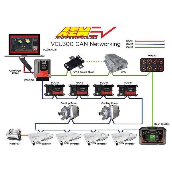
This mindmap illustrates the relationships and primary data flows between the key components in the dual-microcontroller architecture. The VCU acts as the central node, connecting various peripherals and the dedicated Inverter MCU.
The mindmap highlights the VCU's central role in bridging communication between the BMS, MC, Display, Cloud (via SIM module), and the specialized Inverter MCU.
Comparative Functional Load: VCU vs. Inverter MCU
While both microcontrollers are critical, their operational demands differ significantly. The VCU focuses on data handling and coordination, while the Inverter MCU prioritizes high-speed, real-time power electronics control. This radar chart provides a conceptual comparison based on key functional requirements.
As illustrated, the Inverter MCU has extremely high real-time control demands and safety logic implementation focus. In contrast, the VCU handles more diverse tasks involving data aggregation, numerous peripheral interfaces, and complex cloud interactions, though its direct real-time control needs are lower than the inverter's.
Communication Protocols and Data Flow Summary
Effective communication is paramount in this distributed architecture. Different interfaces handle specific data links, ensuring reliability and efficiency.
Key Interfaces
- CAN Bus: The workhorse for automotive inter-module communication. Used for VCU <-> BMS, VCU <-> MC, and Inverter MCU -> VCU links due to its robustness against electrical noise and built-in error handling. Multiple CAN buses might be used (CAN1, CAN2, CAN3 as shown in some examples) to segregate traffic and manage bandwidth.
- SPI/I2C: Common serial protocols for connecting peripherals like the display module to the VCU. Suitable for moderate data rates over short distances.
- UART: Often used for point-to-point serial communication, such as linking the VCU to the SIM/cellular module for cloud data transfer.
Data Flow Table
This table summarizes the primary data movements within the described architecture:
| Data Flow Direction | Source | Destination | Key Data Types | Interface Protocol |
|---|---|---|---|---|
| Read | BMS | VCU | Battery Voltage, SOC, SOH, Cell Voltages, Temperature, Faults | CAN Bus |
| Read | Motor Controller (MC) | VCU | Power Details (Torque, Speed), Motion Status, Faults, Light Status | CAN Bus |
| Push/Read | Inverter MCU | VCU | Inverter Status, Performance Data, Faults | CAN Bus |
| Write | VCU | Display Module | Text, Images, Animations, GUI Updates | SPI / I2C / Parallel |
| Write (Commands) | VCU (Relaying Cloud Cmds) | BMS | Shutdown Command, Lock Motor Command (indirect) | CAN Bus |
| Write (Control) | Inverter MCU | Inverter Power Stage | PWM Signals, Gate Drive Signals | Direct Hardware Lines |
| Stream (Push) | VCU (Aggregated Data) | SIM Module | Telemetry (BMS, MC, Inverter Data) | UART / Other Serial |
| Stream (Push) | SIM Module | Cloud Server | Aggregated Vehicle Telemetry | Cellular (e.g., MQTT over LTE) |
| Stream (Receive) | Cloud Server | SIM Module -> VCU | Remote Commands (e.g., for BMS) | Cellular -> UART -> VCU Processing |
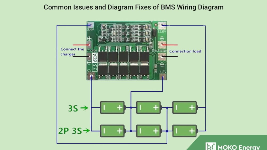
Conceptual illustration showing typical connections in a Battery Management System (BMS), including communication lines (like CAN) often linking to a VCU.
Understanding Microcontroller Architecture Fundamentals
While the specific microcontrollers used (like STM32, NXP S32K, or automotive-specific processors) vary, they share common architectural principles. Understanding these basics helps appreciate how they handle the complex tasks described.
This video provides a general overview of a microcontroller architecture (NXP LPC1768 with ARM Cortex-M core), covering core components like CPU, memory, and peripherals, which are fundamental concepts applicable to the VCU and Inverter MCUs discussed here.
Key Internal Components
- CPU (Central Processing Unit): Executes program instructions. Performance varies based on the core (e.g., ARM Cortex-M, Cortex-R).
- Memory:
- Flash/ROM: Stores the program code (firmware). Non-volatile.
- RAM: Stores temporary data during operation. Volatile.
- Often uses Harvard architecture (separate buses for instructions and data) for improved performance in real-time applications.
- Peripherals: Built-in hardware modules for specific tasks:
- Communication Interfaces: CAN controllers, SPI, I2C, UART modules.
- Timers/Counters: For scheduling tasks, generating PWM signals.
- ADC (Analog-to-Digital Converter): To read sensor values (voltage, temperature).
- GPIO (General Purpose Input/Output): Pins configurable as inputs or outputs.
- Interrupt Controller: Manages hardware interrupts for timely responses to events (e.g., data received on CAN).
Frequently Asked Questions (FAQ)
Why is CAN bus so commonly used in vehicles?
CAN (Controller Area Network) bus is favored in automotive applications due to its robustness, reliability, and cost-effectiveness. Key features include:
- Differential Signaling: Makes it highly resistant to electrical noise common in vehicles.
- Multi-Master Capability: Allows multiple ECUs (Electronic Control Units) like the VCU, BMS, and MC to share the same bus.
- Prioritization: Message IDs determine priority, ensuring critical data gets through first.
- Error Detection & Fault Confinement: Built-in mechanisms detect errors and can isolate faulty nodes.
What kind of microcontrollers are typically used for VCU and Inverter control?
The choice depends on performance needs, safety requirements, and cost:
- VCU: Often uses 32-bit automotive-grade microcontrollers with sufficient processing power, memory, and multiple CAN interfaces. Examples include families like NXP S32K, Infineon AURIX, or STMicroelectronics SPC5/Stellar. Sometimes powerful ARM Cortex-A processors with real-time co-processors are used for very complex VCUs.
- Inverter MCU: Typically requires MCUs with strong real-time capabilities, dedicated peripherals for motor control (e.g., advanced PWM timers, fast ADCs), and safety features. Examples include NXP MPC5xxx series, TI C2000 series, or specialized members of the AURIX or Stellar families designed for powertrain applications.
How is data security handled, especially with cloud connectivity?
Security is crucial. Measures include:
- Secure Communication Protocols: Using TLS/SSL for encrypting data between the SIM module and the cloud server (e.g., MQTT over TLS).
- Authentication: Ensuring only authorized devices and servers can communicate.
- Secure Boot & Firmware Signing: Preventing unauthorized software from running on the VCU.
- Hardware Security Modules (HSMs): Some automotive MCUs include HSMs for secure key storage and cryptographic operations.
- CAN Bus Security: While standard CAN lacks encryption, techniques like message authentication (e.g., CAN-Auth) or segmentation via gateways can add security layers internally.
Could a single, more powerful microcontroller handle all these tasks?
Technically, yes, a very powerful multi-core processor could potentially run all functions. However, the dual-MCU approach offers significant benefits:
- Real-time Determinism: Dedicating an MCU to inverter control ensures critical timing requirements are met without interference from less time-sensitive tasks like display updates or cloud communication.
- Safety & Redundancy: Separating functions improves fault tolerance. An issue in the display driver is less likely to affect critical inverter operation.
- Development Complexity: Managing real-time control, safety functions, communication stacks, and application logic on a single complex processor can be challenging and require sophisticated operating systems and software partitioning (like AUTOSAR).
- Cost Optimization: Using specialized MCUs optimized for their specific tasks can sometimes be more cost-effective than using a single, high-end processor.
Therefore, while possible, the distributed architecture is often preferred for performance, safety, and development reasons in demanding applications like EV control.
Recommended Further Exploration
- What are the differences between CAN FD and Classic CAN, and why might CAN FD be better for modern EV data rates?
- How does the AUTOSAR standard influence the software architecture running on VCUs and other ECUs in EVs?
- What functional safety (ISO 26262) considerations apply to the design of VCUs and inverter controllers?
- How are Over-the-Air (OTA) software updates securely managed for EV control units like the VCU?
References
Last updated May 5, 2025