
Flight Control Report
A comprehensive report on full model, SPO, flight control designs, and autopilot systems
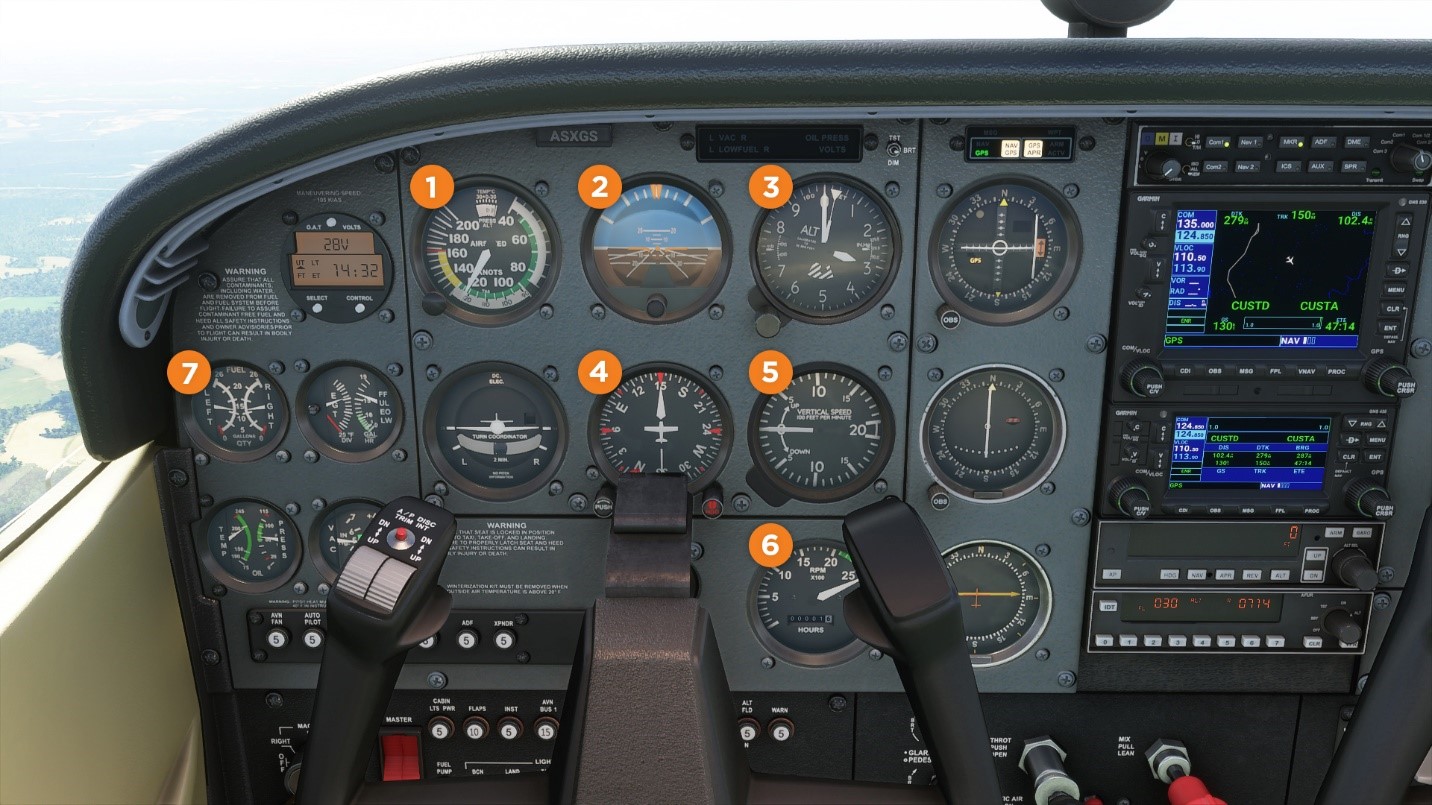
Key Takeaways
- Integrated Modeling: A holistic full aircraft model including dynamic laws and SPO constraints forms the basis for advanced flight control design.
- Design Methodologies: Both classical and modern techniques such as PID, LQR, H∞, and fly-by-wire architectures are used to achieve stability, responsiveness, and safety.
- Autopilot Evolution: Autopilot systems have evolved from simple heading maintenance to highly integrated systems managing every stage of flight with extensive redundancy and guidance algorithms.
Introduction
Flight control systems (FCS) represent a cornerstone in modern aviation, integrating both technology and human interaction to enable safe, efficient, and precise control of aircraft throughout their flight envelope. This report is divided into three major parts. Part 1 elaborates on the full aircraft model with a focus on Single Pilot Operations (SPO) and their implications on flight safety and control performance. Part 2 discusses various flight control designs, ranging from conventional mechanical systems to advanced digital fly-by-wire implementations. Part 3 examines the evolution and design of autopilot systems that extend controlled flight automation from takeoff to landing.
Part 1: Full Model and SPO
Overview of the Full Aircraft Model
The full aircraft model is an integrated representation of an aircraft's dynamic behavior consisting of both translational and rotational motions. Typically, the motion of an aircraft is governed by the Newton-Euler equations, which describe how forces and moments influence the state variables, including position, velocity, attitude angles, and angular rates. This dynamic model provides the necessary framework required for advanced flight control system designs.
Mathematical Formulation and Dynamic Modeling
The state-space representation of the flight dynamics can be expressed in the canonical form:
$$\dot{x} = Ax + Bu,$$
$$y = Cx + Du,$$
where x denotes the state vector incorporating positions, velocities, and attitude parameters, u represents the control inputs through elements like ailerons, elevators, and rudders, and A, B, C, D are matrices derived from the aircraft's physical parameters and aerodynamic properties. Nonlinearities, particularly those inherent in attitude dynamics, are addressed either through exact nonlinear modeling or by linearizing the equations around typical operating points.
Single Pilot Operations (SPO)
Single Pilot Operations (SPO) refer to scenarios where one pilot is charged with the responsibility of overseeing and managing the aircraft’s control functions. The deployment of SPO raises challenges in human factors engineering, as the reduction in crew numbers requires that the single pilot not only handle active control tasks but also supervise system automation and monitor flight-critical parameters.
With increasing automation in modern aircraft, the role of the pilot is transitioning from direct manual control to managing and supervising automated systems. SPO therefore necessitates the flight control system itself to be robust, possessing the ability to maintain stability in various flight conditions, while also providing clear, intuitive interfaces to keep the pilot informed about underlying system statuses.
Integration of SPO with the Full Model
Ensuring safety and efficiency under SPO conditions involves integrating performance optimization constraints (often referenced as SPO constraints) into the dynamic model. These constraints include specifications for steady-state error, overshoot, rise time, and settling time that define the desired performance. The integration process typically employs optimization techniques such as gradient descent, genetic algorithms, or convex optimization methods to tune the aircraft model parameters for achieving the desired performance targets.
Full Model Visualization
The following table summarizes the key components and parameters commonly featured in a full aircraft dynamic model:
| Component | Description | Key Parameters |
|---|---|---|
| Translational Motion | Aircraft’s linear movement in 3D space. | Velocity, acceleration, forces, mass |
| Rotational Motion | Aircraft’s attitude dynamics affecting pitch, roll, and yaw. | Angular rates, moments of inertia, aerodynamic damping |
| Control Surfaces | Actuators such as ailerons, elevators, and rudders for maneuvering. | Deflection angles, actuation efficiency |
| Optimization Parameters | Parameters set by SPO constraints to achieve desired performance. | Steady-state error, overshoot, rise time, settling time |
The above table illustrates how various components integrate to form the full dynamic model crucial for effective flight control.
Part 2: Flight Control Designs
Overview of Flight Control Systems
Flight control designs refer to the methodologies and systems that enable pilots to direct aircraft behavior safely and efficiently. While early systems were purely mechanical in nature, modern aircraft predominantly use electronic systems, including fly-by-wire (FBW) controls, which are managed by digital computers. These digital systems offer enhanced precision, redundancy, and the ability to incorporate advanced algorithms that adapt to dynamic flight conditions.
Historical Evolution: Mechanical to Digital Systems
Initially, flight control systems consisted of mechanical linkages such as cables, pulleys, rods, and chains. In these systems, pilot inputs were directly transmitted to the control surfaces, leaving little room for computational enhancement or adaptability. Although mechanically simple, these designs often suffered from issues related to wear, response times, and lack of redundancy.
With technological advancements, the development of fly-by-wire systems emerged. These digital systems replace mechanical linkages with electrical signals processed by flight control computers. Fly-by-wire systems not only deliver improved accuracy and responsiveness but also incorporate features such as flight envelope protection, which prevents the aircraft from reaching unsafe flight conditions by automatically adjusting control inputs in critical scenarios.
Modern Control Design Techniques
Modern flight control designs employ a variety of control strategies that enhance aircraft performance and stability:
- Classical Control (PID Controllers): These controllers utilize proportional-integral-derivative actions to provide immediate corrective measures on attitude and altitude control. PID controllers are valued for their simplicity and reliable performance in lower complexity systems.
- Linear Quadratic Regulator (LQR): This optimal control approach minimizes a quadratic cost function representing the trade-off between state errors and control magnitudes. The LQR design synthesizes control laws that ensure both efficiency and robust performance in the presence of disturbances.
- H∞ Control: Robust control methods, including H∞ control, focus on guaranteeing system stability under uncertainties and model inaccuracies. These methods are essential when dealing with disturbances and non-modeled dynamics, ensuring safe flight even under adverse conditions.
- Model Predictive Control (MPC): MPC employs advanced algorithms that plan control actions over a future time horizon, based on dynamic predictions of the aircraft’s behavior. This method is particularly effective in achieving optimal performance in multivariable systems while considering constraints related to actuator limits and flight envelope boundaries.
Simulation and Testing Methodologies
The simulation phase plays a crucial role in fine-tuning flight control designs. Software platforms like MATLAB/Simulink enable engineers to simulate the full state-space dynamics of the aircraft, apply SPO constraints, and evaluate control laws under various scenarios. Key testing parameters in these simulations include:
- State Responses: Analysis of position, velocity, and orientation responses to control inputs.
- Tracking Errors: The deviation between desired and actual flight paths, essential for verifying controller accuracy.
- Control Surface Activity: Monitoring the deflections and movements of ailerons, elevators, and rudders to ensure smooth performance with minimal wear and tear.
- Robustness: Assessing the ability of the control system to handle disturbances such as wind or system uncertainties.
Different flight phases—from takeoff to landing—require specialized control designs that dynamically adjust based on the phase of flight. For example, during takeoff, rapid response and ascent performance are crucial, while at cruise, stability and minimal control deflections are prioritized.
Comparative Overview: Mechanical vs. Fly-by-Wire Systems
The evolution from mechanical to digital flight control systems introduced several benefits. The table below contrasts these two categories:
| Aspect | Mechanical Systems | Fly-by-Wire Systems |
|---|---|---|
| Connection Method | Cables, rods, and pulleys | Electronic signals through computer interfaces |
| Precision | Limited by mechanical tolerances | High precision with sensor feedback and computational refinement |
| Redundancy | Minimal redundancy; harder to incorporate backup systems | Multiple redundant computers ensuring safety and reliability |
| Adaptability | Static, with fixed control responses | Dynamic, with integrated flight envelope protection and adaptive controls |
The shift to fly-by-wire has greatly improved flight safety and performance by incorporating advanced control methodologies and enhanced system monitoring capabilities.
Part 3: Autopilot Designs
Overview and Evolution of Autopilot Systems
Autopilot systems are designed to automate aircraft control, thereby reducing pilot workload and increasing overall flight safety. Since their initial development for maintaining a constant heading and altitude, modern autopilot systems have evolved dramatically. Today, they are fully integrated with flight management systems (FMS) and often work in concert with autothrottle mechanisms to provide comprehensive control of the aircraft from takeoff through to landing.
Core Functions of Modern Autopilots
Modern autopilot systems serve multiple roles throughout different flight phases:
- Navigation Tracking: Following pre-programmed flight paths or waypoints based on inputs from the FMS, ensuring accurate route adherence.
- Attitude and Altitude Control: Maintaining the proper aircraft attitude, altitude, and heading with minimal deviations.
- Disturbance Rejection: Automatically adjusting control inputs to counteract external disturbances such as gusts and turbulence, thereby enhancing stability.
- Mode Transitioning: Seamlessly switching between manual and automated control modes. For instance, during unexpected emergencies, pilots can override automated decisions, or in planned transitions like switching from approach to go-around modes.
Design Approaches and Control Algorithms
The design of autopilot systems leverages modern control theory and integrated sensor data to maintain a stable and predictable flight path:
- Optimal Control Techniques: Approaches such as the Linear Quadratic Regulator (LQR) optimize flight performance by minimizing deviations between desired and actual states while balancing the cost of control efforts.
- Digital Signal Processing: Modern autopilots use advanced digital algorithms to process sensor data (from GPS, gyroscopes, and accelerometers) in real-time, ensuring that control decisions remain optimal under varied flight conditions.
- Integrated Guidance Systems: Autopilots often interface with navigation systems to follow specific flight plans. This integration allows for automatic speed adjustments, altitude management, and lateral tracking via ILS or RNAV approaches.
- Adaptive and Redundant Architectures: To enhance reliability, autopilot systems are designed with redundancy. In many cases, multiple independent control paths ensure that, in the event of a single system failure, the aircraft remains controllable and safe.
Practical Implementation and Testing
The implementation of autopilot systems involves rigorous testing and validation in both simulation and real-world environments. Simulators are frequently used to generate flight scenarios that include normal operations, emergency procedures, and adverse weather conditions. This testing validates that the autopilot can maintain control within the acceptable performance envelope.
During the descent and landing phases, autopilot systems dynamically adjust thrust, guide the aircraft along the ILS glide path, and in some instances, even perform fully automated landings known as Autoland. Autoland capabilities integrate precise control of pitch, roll, and yaw with speed and altitude management, ensuring a smooth touchdown even under reduced visibility conditions.
Integration with Flight Management Systems (FMS)
A modern aircraft’s autopilot is not a standalone system. It is tightly integrated into the broader Flight Management System (FMS). This integration enables the autopilot to access extensive navigation data, recent weather updates, and operational constraints. With such integration, the autopilot system can automatically adjust power settings using an autothrottle mechanism, maintain lateral stability with auto-trim adjustments, and even transition into safety modes such as go-around procedures when required.
Safety and Reliability Considerations
The safe and efficient operation of autopilot systems relies on meticulous design and deep understanding of the capabilities and limitations of the automated systems. Failures or anomalies in autopilot systems have, in the past, resulted in critical incidents. As such, modern designs incorporate multiple layers of backup, redundancy mechanisms, and clear indications to pilots regarding the system statuses. Additionally, comprehensive training and procedural adherence are emphasized to ensure that any unexpected behavior is swiftly mitigated through manual intervention if needed.
Conclusion
In this report, we have thoroughly examined the integrated approach to flight control, dividing our discussion into three primary segments: the full aircraft model with SPO considerations, advanced flight control designs, and modern autopilot implementations.
The full aircraft model provides a foundational understanding of how dynamic equations and optimization constraints govern an aircraft's behavior. Incorporation of SPO highlights the evolving role of the pilot in a landscape increasingly defined by automation and streamlined human-machine interaction. Modern flight control designs, transitioning from traditional mechanical systems to sophisticated digital ones, ensure stability, robustness, and responsiveness amidst variable flight conditions. Finally, the evolution of autopilot systems from simple heading control to fully integrated flight management showcases a profound leap in aviation technology, where safety, reliability, and automation converge.
The synthesis of these aspects not only demonstrates state-of-the-art methodologies employed in today's aviation systems but also highlights the essential interplay between theoretical models, practical design implementations, and rigorous testing procedures. These combined efforts guarantee that modern aircraft can safely navigate complex and dynamic environments while offering the pilot enhanced situational awareness and command.
References
- Analysis of Single‐Pilot Intention Modeling in Commercial Aviation - Wiley Online Library
- Aircraft Longitudinal Flight Control - MathWorks
- Autopilot - SKYbrary Aviation Safety
- Aircraft Autopilots - Garmin
- Aircraft Flight Control System - Wikipedia
More
Last updated February 18, 2025