
Comprehensive Guide to GRE/MPLS Encapsulation for ICMP Packets
Understanding the Integration of GRE and MPLS in ICMP Packet Transmission
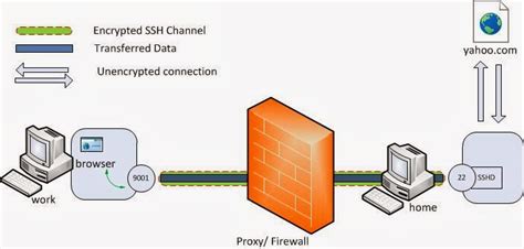
Key Takeaways
- Enhanced Flexibility: GRE/MPLS encapsulation allows ICMP packets to traverse diverse network infrastructures seamlessly.
- Efficient Routing: Combining GRE with MPLS leverages label-switching for optimized packet forwarding and reduced latency.
- Robust Diagnostic Tools: Encapsulating ICMP within GRE/MPLS supports reliable network diagnostics across complex topologies.
Introduction to GRE, MPLS, and ICMP
In the realm of networking, efficient packet transmission across diverse and complex infrastructures is paramount. Three pivotal technologies facilitating this efficiency are Generic Routing Encapsulation (GRE), Multiprotocol Label Switching (MPLS), and the Internet Control Message Protocol (ICMP). Understanding how GRE and MPLS work together to encapsulate ICMP packets is essential for network professionals aiming to optimize network performance and diagnostics.
What is ICMP?
The Internet Control Message Protocol (ICMP) is a fundamental network layer protocol used primarily for diagnostic or control purposes. ICMP facilitates error reporting and operational information exchange between network devices. Common utilities like ping and traceroute rely on ICMP to test connectivity and trace the path of packets across networks.
Understanding GRE
Generic Routing Encapsulation (GRE) is a tunneling protocol developed by Cisco that encapsulates a wide variety of network layer protocols inside virtual point-to-point links over an IP network. GRE creates a virtual point-to-point link by encapsulating the payload of a packet inside a GRE header, followed by an outer IP header. This process allows packets from disparate networks or protocols to traverse a unified physical infrastructure.
Introduction to MPLS
Multiprotocol Label Switching (MPLS) is a high-performance telecommunications network mechanism that directs data from one node to the next based on short path labels rather than long network addresses. MPLS operates at a layer that is generally considered to lie between traditional definitions of Layer 2 (data link layer) and Layer 3 (network layer), often referred to as a "Layer 2.5" protocol. By assigning labels to packets, MPLS simplifies and accelerates the forwarding process, enabling efficient routing and traffic engineering.
The GRE/MPLS Encapsulation Process for ICMP Packets
Encapsulating ICMP packets within GRE and MPLS involves multiple layers of encapsulation to ensure efficient and reliable transmission across complex network infrastructures. This section delineates the step-by-step process of how ICMP packets are encapsulated using GRE and MPLS.
Step 1: ICMP Packet Generation
The process commences when a source device generates an ICMP packet, such as an Echo Request (commonly used in the ping utility). This ICMP packet comprises:
- ICMP Header: Indicates the type (e.g., Echo Request), code, checksum, identifier, and sequence number.
- ICMP Payload: Contains the data sent to the destination, often echoing back received data in Echo Replies.
Step 2: MPLS Encapsulation
Once the ICMP packet is generated, it undergoes MPLS encapsulation at the ingress edge of the MPLS network, typically at a Provider Edge (PE) router. The encapsulation process involves:
- Label Assignment: The MPLS router assigns one or more labels to the ICMP packet based on the routing decision and predetermined label-switching paths.
- Label Stack Formation: Labels are stacked in a hierarchical manner to facilitate hierarchical routing and efficient forwarding through the MPLS domain.
The MPLS-encapsulated packet now contains the original ICMP packet within the MPLS label stack, enabling it to traverse the MPLS network efficiently.
Step 3: GRE Encapsulation
To transmit MPLS-encapsulated ICMP packets over networks that do not support MPLS natively, GRE encapsulation is employed. This involves:
- GRE Header Addition: A GRE header is appended to the MPLS packet, which includes fields such as Protocol Type, Checksum, Key, and Sequence Number (if applicable).
- Outer IP Header Insertion: An outer IP header is added to encapsulate the GRE packet, specifying the source and destination IP addresses of the GRE tunnel endpoints. The Protocol field in this IP header is set to 47, indicating GRE encapsulation.
The final encapsulated packet structure is as follows:
- Outer IP Header: Source and destination IP of the GRE tunnel endpoints.
- GRE Header: Encapsulation details, including protocol type.
- MPLS Label Stack: Labels assigned for efficient routing within the MPLS domain.
- Original ICMP Packet: ICMP header and payload.
Step 4: Transit Through the Non-MPLS Network
With GRE/MPLS encapsulation in place, the packet is now ready to traverse networks that do not inherently support MPLS. Intermediate routers lacking MPLS capabilities process the packet based solely on the outer IP header, unaware of the underlying GRE or MPLS encapsulation. This ensures that the packet can seamlessly navigate through diverse network infrastructures without being hindered by protocol incompatibilities.
Step 5: Decapsulation at the Destination Endpoint
Upon reaching the destination GRE tunnel endpoint, the encapsulation layers are sequentially removed:
- Outer IP Header Removal: The outer IP header is stripped away, revealing the GRE-encapsulated MPLS packet.
- GRE Header Processing: The GRE header is removed, exposing the MPLS label stack.
- MPLS Label Decapsulation: MPLS labels are stripped according to the label-switching rules, restoring the original ICMP packet.
The now-de-encapsulated ICMP packet is forwarded to the intended destination host, where the ICMP processing occurs, such as generating an Echo Reply in response to a ping.
Technical Deep Dive into GRE/MPLS Encapsulation
GRE Header Structure
The GRE header plays a pivotal role in encapsulating packets. Its structure typically includes:
- Checksum: Optional field for error detection.
- Flags: Indicate the presence of optional fields like the Key and Sequence Number.
- Protocol Type: Specifies the type of payload being carried (e.g., 0x8847 for MPLS unicast).
- Key: Optional field used for identifying individual traffic flows within the tunnel.
- Sequence Number: Optional field ensuring packets are processed in order.
For GRE/MPLS encapsulation, the Protocol Type is crucial as it informs the receiving device about the nature of the encapsulated payload, enabling appropriate decapsulation and processing.
MPLS Label Stack
The MPLS label stack assigned during MPLS encapsulation contains one or more labels that dictate the forwarding path within the MPLS domain. Each label in the stack has:
- Label Value: Determines the path the packet will follow.
- Traffic Class: Indicates the priority of the packet.
- Bottom of Stack Bit: Identifies the last label in the stack.
The label stack facilitates efficient routing decisions by allowing routers to forward packets based on labels rather than performing complex IP routing lookups, thereby enhancing network performance.
Integration of GRE and MPLS
Combining GRE with MPLS leverages the strengths of both protocols. GRE provides the flexibility to tunnel MPLS-encapsulated traffic across various network types, while MPLS ensures efficient and scalable label-based forwarding within the MPLS domain. This integration is particularly beneficial in scenarios where service providers need to extend MPLS services over non-MPLS infrastructures or across the public internet.
Benefits of GRE/MPLS Encapsulation
- Protocol Agnosticism: GRE can encapsulate a variety of protocols, making it versatile for different network environments.
- Scalability: MPLS labels enable scalable forwarding decisions, supporting large-scale network deployments.
- Traffic Engineering: MPLS facilitates sophisticated traffic engineering, optimizing network resource utilization.
- Enhanced Diagnostic Capabilities: ICMP encapsulation within GRE/MPLS allows for robust network diagnostics even in complex topologies.
Challenges and Considerations
- Increased Overhead: GRE and MPLS headers add additional bytes to each packet, potentially impacting the Maximum Transmission Unit (MTU).
- Complex Configuration: Implementing GRE/MPLS encapsulation requires meticulous configuration and management.
- Latency Concerns: Additional encapsulation layers can introduce latency, which may be critical for performance-sensitive applications.
- Security Implications: Encapsulated traffic may traverse untrusted networks, necessitating robust security measures such as IPsec.
Mitigating MTU Issues
The increased packet size due to GRE/MPLS encapsulation can lead to fragmentation or "Packet Too Big" ICMP errors if the encapsulated packet exceeds the network's MTU. To mitigate this, network administrators should:
- Adjust MTU Settings: Configure appropriate MTU sizes on network devices to accommodate the additional encapsulation overhead.
- Implement Path MTU Discovery: Enable Path MTU Discovery to dynamically determine the optimal packet size for transmission.
- Optimize Encapsulation Headers: Use minimal GRE and MPLS header configurations to reduce overall packet size.
Practical Use Cases of GRE/MPLS Encapsulation for ICMP Packets
The synergy between GRE and MPLS encapsulation offers numerous practical applications in modern networking environments. Below are some notable use cases:
1. Service Provider Networks
Service providers utilize GRE/MPLS encapsulation to extend their MPLS-based services over diverse customer networks and the public internet. This enables them to offer scalable VPN services, ensuring that ICMP-based diagnostic tools function reliably across the extended network.
2. Enterprise WAN Connectivity
Large enterprises with geographically dispersed offices leverage GRE/MPLS to interconnect their Wide Area Networks (WANs). Encapsulating ICMP packets ensures consistent network diagnostics and monitoring across all interconnected sites.
3. Data Center Interconnects
Data centers interconnected via GRE/MPLS tunnels benefit from enhanced traffic engineering and efficient handling of ICMP traffic. This setup supports high-performance applications requiring reliable and swift network diagnostics.
4. Cloud Networking
Cloud service providers employ GRE/MPLS encapsulation to manage ICMP traffic between their infrastructure and client networks. This ensures seamless connectivity and reliable diagnostics in hybrid cloud environments.
5. Disaster Recovery and Redundancy
In disaster recovery setups, GRE/MPLS tunnels facilitate the transmission of ICMP packets for monitoring and failover mechanisms, ensuring that backup systems remain operational and can be promptly activated when needed.
Configuration Example: Setting Up GRE/MPLS Encapsulation for ICMP Traffic
To illustrate the practical implementation of GRE/MPLS encapsulation for ICMP packets, consider a basic configuration scenario on Cisco IOS devices. This example outlines the steps to configure GRE tunnels and enable MPLS on the relevant interfaces.
Prerequisites
- Cisco IOS-enabled routers at both tunnel endpoints.
- Basic network configuration with IP connectivity between routers.
- MPLS enabled on the core network routers.
Step-by-Step Configuration
1. Configuring the GRE Tunnel Interface
    ! On Router A
    interface Tunnel0
     ip address 10.0.0.1 255.255.255.252
     tunnel source 192.168.1.1
     tunnel destination 192.168.2.1
     tunnel mode gre ip
    !
    ! On Router B
    interface Tunnel0
     ip address 10.0.0.2 255.255.255.252
     tunnel source 192.168.2.1
     tunnel destination 192.168.1.1
     tunnel mode gre ip
2. Enabling MPLS on Interfaces
    ! On both Routers
    mpls ip
    !
    interface GigabitEthernet0/0
     ip address 192.168.1.1 255.255.255.0
     mpls ip
    !
    interface GigabitEthernet0/1
     ip address 192.168.2.1 255.255.255.0
     mpls ip
    !
3. Configuring MPLS Label Distribution
    ! Enable MPLS LDP (Label Distribution Protocol)
    mpls label protocol ldp
    !
    ! On both Routers
    router ospf 1
     network 192.168.1.0 0.0.0.255 area 0
     network 192.168.2.0 0.0.0.255 area 0
    !
    mpls ldp router-id Loopback0 force
    !
4. Verifying the Configuration
    ! Verify GRE Tunnel Status
    show interface Tunnel0

    ! Check MPLS LDP bindings
    show mpls ldp bindings

    ! Display MPLS forwarding table
    show mpls forwarding-table

    ! Test ICMP Traversal
    ping 10.0.0.2
This configuration sets up a GRE tunnel between Router A and Router B, enables MPLS on relevant interfaces, and ensures that ICMP packets can traverse the network seamlessly with GRE/MPLS encapsulation.
Advantages of Using GRE/MPLS for ICMP Encapsulation
- Protocol Flexibility: GRE's ability to encapsulate various protocols complements MPLS's label-switching efficiency, enabling versatile network designs.
- Scalability: MPLS facilitates scalable network architectures, allowing for the management of large volumes of ICMP traffic without performance degradation.
- Improved Network Visibility: Encapsulation aids in monitoring and diagnostics, providing clear insights into ICMP traffic flows and potential network issues.
- Enhanced Security: By encapsulating ICMP within GRE tunnels, organizations can implement additional security measures, such as IPsec, to protect diagnostic traffic.
Potential Drawbacks and Mitigation Strategies
While GRE/MPLS encapsulation offers numerous benefits, it also presents certain challenges that must be addressed to maintain optimal network performance.
Increased Overhead
Encapsulating ICMP packets within GRE and MPLS adds extra headers to each packet, increasing the overall size. This overhead can lead to MTU mismatches, resulting in packet fragmentation or loss.
Mitigation Strategies
- MTU Optimization: Adjust MTU settings across the network to accommodate the additional encapsulation overhead.
- Path MTU Discovery: Utilize Path MTU Discovery to dynamically identify the optimal packet size for transmission without fragmentation.
- Fragmentation Avoidance: Configure routers to manage fragmentation proactively, minimizing the chances of "Packet Too Big" errors.
Configuration Complexity
Implementing GRE/MPLS encapsulation requires meticulous configuration and coordination between network devices. Misconfigurations can lead to connectivity issues and degraded network performance.
Mitigation Strategies
- Standardized Configuration Procedures: Develop and adhere to standardized configuration templates to ensure consistency across devices.
- Comprehensive Testing: Conduct thorough testing in controlled environments before deploying configurations into production networks.
- Automated Configuration Management: Utilize configuration management tools to automate and validate configurations, reducing the risk of human error.
Security Concerns
Encapsulating ICMP traffic within GRE/MPLS tunnels can expose the network to security threats if not adequately protected. Unauthorized access to tunnels can lead to interception or tampering of diagnostic traffic.
Mitigation Strategies
- Implement IPsec: Secure GRE tunnels with IPsec encryption to protect encapsulated traffic from unauthorized access and tampering.
- Access Control Lists (ACLs): Configure ACLs to restrict tunnel endpoint access to trusted devices and networks.
- Regular Audits and Monitoring: Perform routine security audits and monitor tunnel usage to detect and respond to potential security breaches promptly.
Best Practices for Managing GRE/MPLS Encapsulation
Adhering to best practices ensures the efficient and secure operation of GRE/MPLS encapsulated networks handling ICMP traffic.
1. Proper Planning and Design
Meticulous network planning and design are fundamental to successful GRE/MPLS encapsulation. Considerations should include:
-
Capacity Planning: Assess network capacity to handle additional encapsulation overhead.
-
Redundancy and Failover: Design redundancy into the network to maintain connectivity in case of tunnel or device failures.
-
Topology Considerations: Ensure that the network topology accommodates GRE/MPLS tunnels without creating routing loops or bottlenecks.
2. Consistent Configuration Standards
Maintaining consistent configuration standards across all network devices simplifies management and troubleshooting. Establish and enforce configuration guidelines to ensure uniformity.
3. Regular Monitoring and Maintenance
Implement robust monitoring systems to track the performance and health of GRE/MPLS tunnels. Regular maintenance activities, such as firmware updates and configuration reviews, help sustain network reliability.
4. Security Enhancements
Deploy comprehensive security measures to protect encapsulated ICMP traffic. This includes encryption, access controls, and continuous security assessments to identify and address vulnerabilities.
5. Documentation and Training
Maintain detailed documentation of network configurations, encapsulation procedures, and troubleshooting protocols. Additionally, provide training for network administrators to ensure proficiency in managing GRE/MPLS encapsulated networks.
Conclusion
GRE/MPLS encapsulation for ICMP packets is a sophisticated technique that enhances the flexibility, scalability, and efficiency of modern networking infrastructures. By leveraging GRE's tunneling capabilities with MPLS's label-switching efficiency, organizations can ensure reliable transmission and diagnostic capabilities across diverse and complex network environments. While the implementation of GRE/MPLS encapsulation introduces certain challenges, adherence to best practices and proactive management strategies can mitigate these issues, resulting in robust and high-performing networks.
References
Last updated January 18, 2025