
HP ML350P G8 Motherboard Supply Voltages
Detailed Overview and Labeled Diagram of Power Distribution
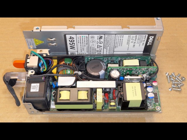
Key Highlights
- Power Rails & Connectors: Documentation of +12V, +5V, +3.3V, and specialized rails like chipset and memory voltages.
- Diagram Interpretation: A labeled diagram detailing the connections between power supplies and motherboard components.
- Redundancy & Specifications: Explanation of redundancy measures and specific supply connector details ensuring reliable operation.
Overview of Supply Voltages and Connector Types
The HP ProLiant ML350P Gen8 server is engineered to offer robust performance for diverse business workloads. At the heart of this server lies a sophisticated motherboard that receives multiple power voltages from the power supply unit (PSU). These power rails serve distinct functions, allowing key devices such as the CPU, chipset, memory, PCIe devices, and standby circuits to operate at their optimal voltage levels. Manufacturers design these systems with built-in redundancy to ensure continuity of service even in the event of a power supply fault.
The power distribution to the motherboard is achieved via several connectors typically found in ATX-based servers. They include the ATX main power connector, the dedicated CPU power connector, and additional connectors for components such as memory modules, chipset circuitry, and PCIe expansion cards. The following sections provide a comprehensive breakdown of these voltages, their functions, and their connection points on the HP ML350P G8 motherboard.
Reviewed Power Supply Voltages
The ML350P G8 motherboard receives various voltage rails: +12V – Primarily drives high-power devices such as the CPU, memory, and PCIe components. This rail is furnished through the main ATX connector and supplemented by dedicated power connections. +5V – Supplies components that need lower power inputs like USB ports, storage interfaces, and some chipset elements. +3.3V – Integral to powering the onboard logic circuits, low-draw peripheral devices, and memory modules. Additional voltage levels are dedicated to specialized components: 1.05V and 1.2V – Typically allocated for powering the chipset and CPU-specific elements in a controlled environment. Standby Voltage (5VSB) and VBAT: Ensures key features remain powered, such as the system clock (RTC), even when the main system is off.
Labeled Diagram: Power Distribution on the HP ML350P G8 Motherboard
Text-Based Diagram Overview
Below is a detailed text-based diagram that maps the flow of power from the PSU to critical components on the HP ML350P G8 motherboard:
         +-------------------------------------------+
         |              Power Supply Unit            |
         |              (Multiple Redundant PSUs)    |
         +-------------------------------------------+
                           │
                           │
                           ▼
         +-------------------------------------------+
         |             ATX Main Power Connector      |
         |           (+12V, +5V, +3.3V Rails)         |
         +-------------------------------------------+
                           │
             ┌─────────────┴─────────────┐
             │                           │
             ▼                           ▼
    +------------------+         +------------------+
    |  CPU Power       |         |  Chipset Power   |
    |  Connector       |         |  Connector       |
    |  (8-pin / 4+4)   |         |  (+1.05V, +1.2V)  |
    +------------------+         +------------------+
             │                           │
             ▼                           ▼
    +------------------+         +------------------+
    |     CPU          |         |    Chipset       |
    |  (12V, 5V,3.3V)  |         |  (Managed Voltages|
    +------------------+         |  for onboard ICs) |
             │                           │
             └─────────────┬─────────────┘
                           │
                           ▼
         +-------------------------------------------+
         |           Memory & Expansion Rails        |
         |  Memory Connector (1.2V, 1.35V for DRAM)    |
         |  PCIe Connector (Typically 12V, 3.3V)        |
         +-------------------------------------------+
                           │
                           ▼
         +-------------------------------------------+
         |        Standby/Low-Power Devices          |
         |  (VBAT for RTC; 5VSB for standby power)     |
         +-------------------------------------------+
Each block in this diagram represents a key interface where the PSU-powered voltage is distributed to specific components on the motherboard. Note that while the main ATX connector carries the broad strokes of +12V, +5V, and +3.3V, specialized connectors are tailored for the CPU and chipset to ensure stable power delivery essential for reliable operation.
Detailed Voltage Supply Components
ATX Main Power Connector
The ATX main power connector is the primary conduit for delivering power to the motherboard. It consolidates:
- +12V Rail: Vital for high demand components like the CPU and PCIe objects.
- +5V Rail: Supplies lower-power devices including some storage interfaces and USB.
- +3.3V Rail: Essential for on-board logic circuits, certain memory functionalities, and subsystem controllers.
This connector ensures that the varying needs of the motherboard’s circuits are met concurrently, balancing high-power and low-power domains.
CPU Power Connector
The dedicated CPU power connector, often found as an 8-pin or 4+4 pin configuration, directly supports the central processing unit. Its design caters to rapid fluctuations in power demands during high processing tasks. The connector mostly relays the +12V supply along with supplemental +5V and +3.3V where necessary.
Chipset Power Connector
Specialized connectors for the chipset deliver precise voltages that may include low-voltage rails such as 1.05V or 1.2V, ensuring that the chipset’s integrated circuits function with minimal thermal stress and maximal stability. The allocation of a dedicated power rail minimizes interference with other components on the motherboard.
Memory and PCIe Connectors
Memory modules typically operate on very specific voltage levels, often in the realm of 1.2V or 1.35V for DDR3 modules in this server. Dedicated connectors and power rails help in maintaining these voltage levels to enhance stability and overall performance.
Similarly, PCIe connectors for expansion cards deliver both 12V and 3.3V power. The 12V supply generally supports higher-powered peripherals while the 3.3V rail assists in supplying auxiliary voltage to these devices.
Standby and Battery Backup
Certain components, such as the system clock (RTC) and other low-power circuits, require continuous power even when the main system is off. This is achieved through a small battery (commonly referred to as VBAT) along with a standby voltage (5VSB). These elements are essential for maintaining system settings and low-level functions without complete power-down.
Comprehensive Table: Voltage Distribution Overview
| Component | Voltage Levels | Connector/Interface | Purpose |
|---|---|---|---|
| Main ATX | +12V, +5V, +3.3V | 24-pin ATX Connector | General motherboard and peripheral supply |
| CPU | +12V, (Supplementary +5V, +3.3V) | 8-pin / 4+4 Connector | Direct CPU power for processing tasks |
| Chipset | 1.05V, 1.2V | Dedicated Chipset Connector | Chipset logic and controller circuitry |
| Memory | 1.2V, 1.35V | Memory Power Connector | DDR3 memory modules stability |
| PCIe Expansion | 12V, 3.3V | PCIe Power Connector | Expansion cards/peripherals support |
| Standby/Battery | 5VSB, VBAT (Typically 3.3V or 5V) | Standby Connector & Coin-Cell Battery | Maintaining RTC and basic functions |
Additional Insights on Configuring and Maintaining Power Supply
Redundancy and Safety Features
The ML350P G8 server is designed to support multiple power supplies. It is important to note that while the server may have redundant power modules (commonly rated at 460W each), they function independently to ensure that if one power supply fails, the remaining supplies continue to operate without a combined wattage sum. This built-in redundancy is critical in maintaining continuous uptime in mission-critical environments.
Many HP servers recommend using a high-quality power distribution unit (PDU) to manage potential ground-leakage currents particularly in multi-unit setups. A properly installed PDU not only optimizes the power consumption but also significantly improves the safety and reliability of the overall server infrastructure.
Monitoring and Diagnostics
The server’s integrated management tools, such as the Systems Insight Display and iLO (Integrated Lights-Out), provide real-time information about the power status. LEDs on the server's front panel indicate fault conditions, degraded states, or critical power supply issues. If any anomaly in voltage levels or power distribution is detected, the management software logs provide additional error messages that help in quick diagnostics and troubleshooting.
Documentation and References
For detailed technical specifics including the exact voltage figures and connector layouts, consulting the official HP documentation is highly recommended. Manuals and service guides provide schematics and reference diagrams which are regularly updated to reflect changes in hardware revisions and power supply configurations.
The accuracy of the diagram and voltage data is based on typical configurations seen in HP ML350P Gen8 systems. Exact values may vary slightly based on the system configuration and component tolerances.
References
- HP ProLiant ML350p Gen8 Manual - Manualslib
- HP ProLiant ML350p Gen8 Product Support - HPE
- HP ML350p Gen8 User Manual - Newegg
- HP ProLiant ML350p Gen8 Overview - HPE Community
- HP ML350p Gen8 Power Supply Kit Discussion - Spiceworks
Recommended Related Queries
 images10.newegg.com

Last updated March 22, 2025