
Understanding Induced Electromotive Force in a Changing Magnetic Field
Exploring Faraday's Law and Lenz's Law in Electromagnetic Induction
Key Insights
- Induced emf is generated when there is a change in magnetic flux through a loop or coil.
- Faraday's Law quantifies the magnitude of the induced emf, stating it is proportional to the rate of change of magnetic flux.
- Lenz's Law determines the direction of the induced current and emf, indicating it opposes the change in magnetic flux that produced it.
When a circular region is subjected to a changing magnetic field, an electromotive force (emf) is induced around its border. This phenomenon is a fundamental principle of electromagnetic induction, governed by Faraday's Law and Lenz's Law. Faraday's Law describes the magnitude of the induced emf based on the rate of change of magnetic flux, while Lenz's Law provides the direction of the induced current and emf, ensuring it opposes the change in magnetic flux.
The Concept of Magnetic Flux
Before delving into induced emf, it's crucial to understand magnetic flux. Magnetic flux (\(\Phi_B\)) is a measure of the total magnetic field lines passing through a given area. It is defined as the product of the magnetic field strength (B), the area (A) through which the field lines pass, and the cosine of the angle (\(\theta\)) between the magnetic field vector and the area vector:
\[ \Phi_B = B \cdot A \cdot \cos(\theta) \]The units of magnetic flux are Tesla-square meters (T⋅m²), also known as Webers (Wb).
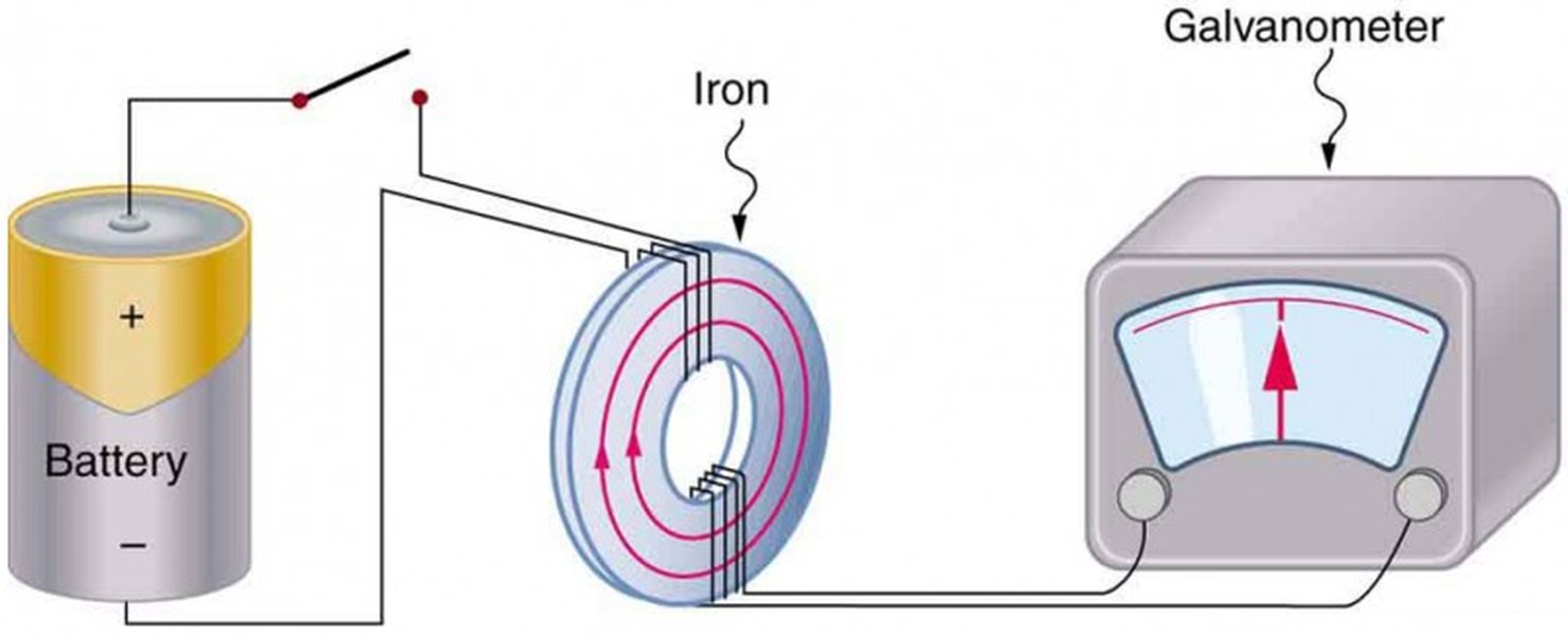
Magnetic flux depends on the magnetic field strength, the area, and the angle between the field and the area vector.
Factors Affecting Magnetic Flux
Magnetic Field Strength (B)
A stronger magnetic field means more magnetic field lines per unit area, resulting in greater magnetic flux.
Area (A)
A larger area exposed to the magnetic field will intercept more magnetic field lines, leading to increased magnetic flux.
Angle (\(\theta\))
The orientation of the area relative to the magnetic field is crucial. Magnetic flux is maximum when the magnetic field lines are perpendicular to the area (angle is 0° or 180°, cos(\(\theta\)) = ±1), and zero when the field lines are parallel to the area (angle is 90°, cos(\(\theta\)) = 0).
Faraday's Law of Induction
Faraday's Law states that the magnitude of the induced emf (\(\mathcal{E}\)) in a circuit is directly proportional to the rate of change of magnetic flux through the circuit. Mathematically, this is expressed as:
\[ \mathcal{E} = -N \frac{\Delta \Phi_B}{\Delta t} \]Where:
- \(\mathcal{E}\) is the induced emf (in volts, V).
- N is the number of turns in the coil (for a single loop, N = 1).
- \(\Delta \Phi_B\) is the change in magnetic flux (in Webers, Wb).
- \(\Delta t\) is the time interval over which the change occurs (in seconds, s).
The negative sign in Faraday's Law is a consequence of Lenz's Law, which dictates the direction of the induced emf and current.
Calculating the Change in Magnetic Flux
To calculate the induced emf, we first need to determine the change in magnetic flux. The change in magnetic flux (\(\Delta \Phi_B\)) is the difference between the final magnetic flux (\(\Phi_{B, \text{final}}\)) and the initial magnetic flux (\(\Phi_{B, \text{initial}}\)):
\[ \Delta \Phi_B = \Phi_{B, \text{final}} - \Phi_{B, \text{initial}} \]Each magnetic flux value is calculated using the formula \(\Phi_B = B \cdot A \cdot \cos(\theta)\) at the respective initial and final states.
Lenz's Law: Determining the Direction of Induced Current and EMF
Lenz's Law provides the direction of the induced current and emf. It states that the direction of the induced current in a circuit is such that it opposes the change in magnetic flux that produced it. This law is a manifestation of the conservation of energy.

Lenz's Law explains how the induced current creates a magnetic field that opposes the change in the external magnetic field.
Applying Lenz's Law and the Right-Hand Rule
To determine the direction of the induced current and emf using Lenz's Law, we often use the right-hand rule. There are several variations of the right-hand rule, but a common application in this context is as follows:
- Identify the direction of the external magnetic field and how it is changing (increasing or decreasing).
- According to Lenz's Law, the induced current will create a magnetic field that opposes this change. If the external flux is increasing into the page, the induced field will be out of the page. If the external flux is decreasing into the page, the induced field will be into the page.
- Use the right-hand rule for magnetic fields created by currents: Curl your fingers in the direction of the induced current. Your thumb will point in the direction of the induced magnetic field. By aligning your thumb with the desired induced magnetic field (from step 2), your curled fingers will show the direction of the induced current around the loop.
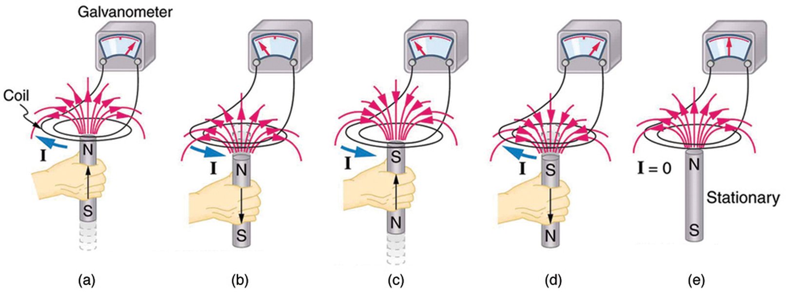
The right-hand rule helps determine the direction of the magnetic field produced by a current.
Calculating the Average Induced EMF for the Specific Scenario
Let's apply these principles to the user's specific query. We have a circular region, and the magnetic field is changing in magnitude and direction over a given time period.
Initial Conditions
The initial magnetic field magnitude and direction are not explicitly given in the prompt, but we are told that "Immediately after this," the field changes. We will assume the initial state is just before the change described.
Final Conditions
-
Final Magnetic Field Magnitude (\(B_{\text{final}}\)): 0.500 T
-
Final Magnetic Field Direction: Downward (when viewed from above)
-
Time Interval (\(\Delta t\)): 85.0 ms = 0.085 s
The prompt refers to a "circular region," implying a specific area. Let's assume the area of this circular region remains constant during the time interval. However, the radius or diameter of this circular region is not provided. To proceed with a numerical calculation of the induced emf, we need the area of the loop. Let's denote the radius of the circular region as \(r\). The area \(A\) would be \(\pi r^2\).
Also, we need the initial magnetic field's magnitude and direction to calculate the initial magnetic flux. Since these are not provided, we cannot calculate a specific numerical answer for the induced emf magnitude. However, we can outline the steps for the calculation and explain the direction.
Calculating the Initial Magnetic Flux (\(\Phi_{B, \text{initial}}\))
Let \(B_{\text{initial}}\) be the initial magnetic field magnitude and \(\theta_{\text{initial}}\) be the angle between the initial magnetic field and the area vector. The initial magnetic flux is:
\[ \Phi_{B, \text{initial}} = B_{\text{initial}} \cdot A \cdot \cos(\theta_{\text{initial}}) \]The direction of the area vector is typically taken as perpendicular to the plane of the loop. If we view from above, and the loop is horizontal, the area vector can be pointing either upward or downward. Let's assume the area vector points upward for consistency in applying the direction rules.
Calculating the Final Magnetic Flux (\(\Phi_{B, \text{final}}\))
The final magnetic field is 0.500 T pointing downward. If the area vector is upward, the angle between the downward magnetic field and the upward area vector is 180°. So, \(\theta_{\text{final}} = 180^\circ\), and \(\cos(180^\circ) = -1\).
\[ \Phi_{B, \text{final}} = B_{\text{final}} \cdot A \cdot \cos(\theta_{\text{final}}) = (0.500 \text{ T}) \cdot (\pi r^2) \cdot (-1) = -0.500 \pi r^2 \]Calculating the Change in Magnetic Flux (\(\Delta \Phi_B\))
\[ \Delta \Phi_B = \Phi_{B, \text{final}} - \Phi_{B, \text{initial}} = -0.500 \pi r^2 - (B_{\text{initial}} \cdot \pi r^2 \cdot \cos(\theta_{\text{initial}})) \] \[ \Delta \Phi_B = \pi r^2 (-0.500 - B_{\text{initial}} \cos(\theta_{\text{initial}})) \]Calculating the Average Induced EMF (\(\mathcal{E}_{\text{avg}}\))
Assuming N=1 for a single loop, the average induced emf is:
\[ \mathcal{E}_{\text{avg}} = -\frac{\Delta \Phi_B}{\Delta t} = -\frac{\pi r^2 (-0.500 - B_{\text{initial}} \cos(\theta_{\text{initial}}))}{0.085 \text{ s}} \] \[ \mathcal{E}_{\text{avg}} = \frac{\pi r^2 (0.500 + B_{\text{initial}} \cos(\theta_{\text{initial}}))}{0.085} \]Without the initial magnetic field details (\(B_{\text{initial}}\) and \(\theta_{\text{initial}}\)) and the radius (\(r\)), we cannot provide a specific numerical value for the magnitude of the average induced emf. The magnitude will be in Volts (V), which can then be converted to microvolts (\(\mu\)V) by multiplying by \(10^6\).
For example, if we assume the initial magnetic field was 0.200 T pointing upward (\(\theta_{\text{initial}} = 0^\circ\)) and the radius is 0.10 m, then:
\[ A = \pi (0.10 \text{ m})^2 = 0.01 \pi \text{ m}^2 \] \[ \Phi_{B, \text{initial}} = (0.200 \text{ T}) \cdot (0.01 \pi \text{ m}^2) \cdot \cos(0^\circ) = 0.002 \pi \text{ Wb} \] \[ \Phi_{B, \text{final}} = -0.500 \cdot (0.01 \pi \text{ m}^2) = -0.005 \pi \text{ Wb} \] \[ \Delta \Phi_B = -0.005 \pi - 0.002 \pi = -0.007 \pi \text{ Wb} \] \[ \mathcal{E}_{\text{avg}} = -\frac{-0.007 \pi \text{ Wb}}{0.085 \text{ s}} \approx 0.2585 \text{ V} \]In microvolts, this would be \(0.2585 \times 10^6 \, \mu\text{V} = 258500 \, \mu\text{V}\). This is just an illustrative example, and the actual value depends on the missing initial parameters.
Determining the Direction of the Induced EMF (as seen from above)
The magnetic field changes from some initial state to 0.500 T pointing downward. Assuming the initial magnetic field had an upward component or was smaller in magnitude downward, the change in magnetic flux is an increase in the downward magnetic flux through the loop (or a decrease in upward flux, which is equivalent to an increase in downward flux). Since the area vector is assumed to be upward, a downward magnetic field corresponds to a negative magnetic flux (\(\Phi_B = B \cdot A \cdot \cos(180^\circ) = -BA\)). Therefore, if the initial downward flux was less negative (closer to zero or positive if the initial field had an upward component), the change in flux (\(\Delta \Phi_B\)) will be negative.
According to Lenz's Law, the induced current will create a magnetic field that opposes this change. To oppose an increase in downward magnetic flux, the induced magnetic field must point upward.
Using the right-hand rule: Point your thumb upward (the direction of the induced magnetic field). Your fingers will curl in the direction of the induced current around the loop as seen from above. If your thumb points up (out of the page if the page represents the loop), your fingers curl in a counter-clockwise direction.
Therefore, the direction of the induced current and emf around the border of the circular region, as seen from above, is counter-clockwise.
Summary of Calculations and Direction
Without the initial magnetic field conditions and the radius of the circular region, we cannot provide a numerical magnitude for the average induced emf. However, the formula for the magnitude of the average induced emf is:
\[ |\mathcal{E}_{\text{avg}}| = \left| \frac{\pi r^2 (0.500 + B_{\text{initial}} \cos(\theta_{\text{initial}}))}{0.085} \right| \]Where \(r\) is the radius of the loop in meters, \(B_{\text{initial}}\) is the initial magnetic field magnitude in Teslas, and \(\theta_{\text{initial}}\) is the angle between the initial magnetic field and the upward area vector.
The direction of the induced emf and current, as seen from above, is counter-clockwise.
Related Concepts and Applications
The principles of induced emf and magnetic flux are fundamental to many electrical technologies. Electric generators, for instance, work by rotating coils of wire in a magnetic field, inducing an emf and generating electrical energy. Transformers utilize changing magnetic flux to change voltage levels in AC circuits. These concepts also play a role in understanding phenomena like eddy currents and induction heating.
Motional EMF
Induced emf can also be generated by the motion of a conductor in a magnetic field. This is known as motional emf. The magnitude of the motional emf induced in a straight conductor of length \(L\) moving with velocity \(v\) perpendicular to a magnetic field \(B\) is given by:
\[ \mathcal{E} = B \ell v \]This is a specific case of Faraday's Law where the change in flux is caused by the change in area swept by the moving conductor in the magnetic field.
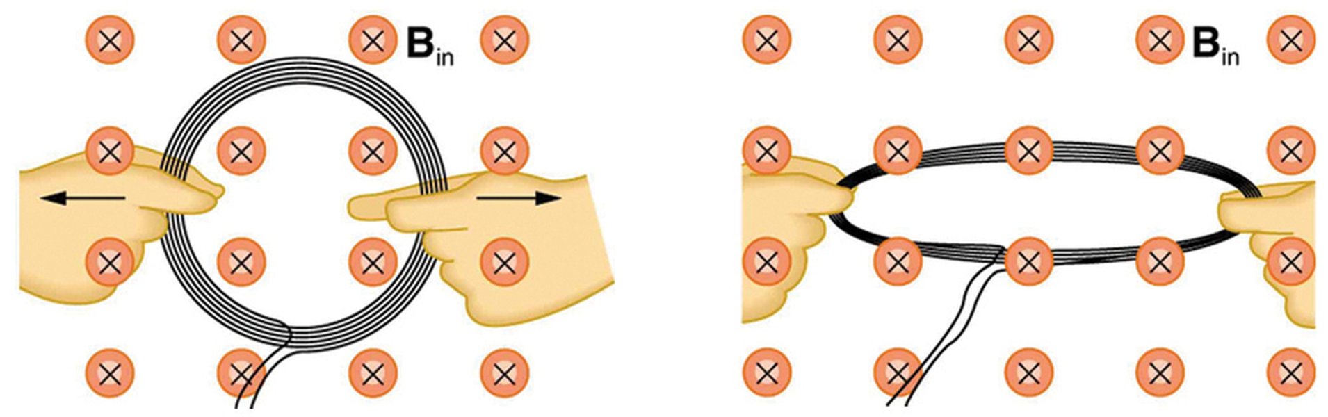
Motional emf is induced when a conductor moves through a magnetic field.
FAQs
What is the difference between magnetic flux and magnetic field strength?
Magnetic field strength (B) is a vector quantity that describes the strength and direction of a magnetic field at a point in space. Magnetic flux (\(\Phi_B\)) is a scalar quantity that represents the total number of magnetic field lines passing through a given area. Magnetic flux depends on the magnetic field strength, the area, and the orientation between the field and the area.
Can induced emf be generated by a stationary magnetic field?
No, a stationary magnetic field alone cannot induce an emf. According to Faraday's Law, an emf is induced only when there is a *change* in magnetic flux through a circuit. This change can be caused by a changing magnetic field strength, a change in the area of the loop exposed to the field, or a change in the orientation between the field and the loop.
How is Lenz's Law related to the conservation of energy?
Lenz's Law is a consequence of the conservation of energy. If the induced current were to create a magnetic field that *aided* the change in magnetic flux, it would lead to a runaway situation where the induced current and the changing flux would reinforce each other, generating an infinite amount of energy, which violates the conservation of energy.
References
Last updated May 1, 2025