
Heat Transfer Coefficient for Inorganic Salt Cooling with Chilled Water
Understanding the Thermal Dynamics of Inorganic Salt and Chilled Water Systems
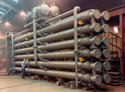
Key Highlights
- Enhanced Performance with Forced Convection: Techniques such as forced convection can dramatically improve the heat transfer coefficient.
- Multiple Design Enhancements: Incorporating fins, metal foams, or a copper matrix significantly amplifies the performance.
- Importance of Operational Conditions: Factors like fluid properties, flow rates, and temperature gradients are vital to optimizing heat transfer.
Understanding the Heat Transfer Coefficient
The heat transfer coefficient (U) is a measure of how efficiently heat is conducted from one medium to another. It is expressed in units of watts per square meter per Kelvin [W/(m²K)] and is a crucial parameter in designing and analyzing heat exchangers, particularly in systems where inorganic salts are used in conjunction with chilled water. The overall performance in such systems hinges on the combined effects of the physical properties of the fluids, the design of the heat exchanger, and the operational conditions.
The Role of Inorganic Salts
Inorganic salts are often chosen in cooling applications due to their favorable thermal properties. Their high thermal capacity and stability make them a viable alternative to conventional fluids. In systems where inorganic salts are cooled using chilled water, the salts serve as the primary heat carrier while the chilled water facilitates the removal of heat. The selection of the salt type, its concentration, and its specific thermal properties all contribute significantly to the overall heat transfer rate. Salt mixtures, particularly hyper-eutectic compositions, tend to show better performance when used in forced convection scenarios, often exhibiting dramatic increases in the heat transfer coefficient.
Chilled Water as a Coolant
Chilled water is widely utilized in industrial cooling applications due to its ready availability, cost-effectiveness, and high specific heat capacity. When used in tandem with inorganic salts, chilled water provides a robust means of dissipating the absorbed heat. The chilled water’s properties, such as its density and flow characteristics, ensure that even minor temperature differences drive significant convective currents. Typical heat transfer coefficients for water-based systems range between 600 and 1500 W/(m²K) but can vary significantly depending on the design and operating conditions of the heat exchanger.
Factors Influencing the Heat Transfer Coefficient
1. Type of Heat Exchanger
The configuration of the heat exchanger plays a pivotal role in determining its efficiency. Shell and tube, plate, and spiral heat exchangers each offer different advantages. The design determines the available surface area for heat exchange and the overall effectiveness of the system. Inorganic salt systems tend to benefit from tailored designs that maximize surface contact while minimizing thermal resistance.
2. Fluid Properties
Both the inorganic salt and the chilled water have distinct thermal and physical properties, including viscosity, density, and specific heat capacity. These properties affect the flow dynamics and, consequently, the heat transfer efficiency. A higher fluid velocity generally leads to turbulent flow, which is favorable for enhancing thermal performance.
3. Flow Conditions and Forced Convection
Flow conditions are among the most critical contributors to the heat transfer coefficient. Employing forced convection—where fluids are actively pumped or circulated—can enhance thermal performance dramatically. For instance, specific designs using forced convection in inorganic salt systems have resulted in tenfold increases in the heat transfer coefficient. This enhancement is primarily due to improved turbulence and more effective mixing of the fluid.
4. Design Enhancements: Fins and Metal Foam
Incorporating design modifications, such as finned tubes or metal foam, significantly increases the available heat transfer surface area. Metal foam, often utilized within a copper matrix, has been shown to escalate the heat transfer coefficient by as much as 28 times. Meanwhile, finned structures can be particularly effective in settings where there is a disparity between the internal and external convective heat transfer conditions.
5. Temperature Gradient and Operating Conditions
The difference in temperatures between the inorganic salt and the chilled water is a driving force in the heat transfer process. A larger temperature difference increases the rate of heat exchange. However, maintaining a consistent temperature gradient is crucial as variations can lead to suboptimal performance or even induce fouling on the heat exchanger surfaces.
6. Fouling and Maintenance Issues
Fouling, primarily from the deposition of inorganic compounds or scaling on surfaces, acts as a thermal barrier and can significantly lower the efficiency of the heat exchange process. Regular maintenance and proper water treatment can mitigate fouling, ensuring that the overall heat transfer coefficient remains high over time.
Quantitative Analysis and Calculation
Basic Formula for Heat Transfer
A central relationship for calculating the heat exchange in a system is:
\( q = U \cdot A \cdot \Delta T \)
where:
- \( q \) is the heat transfer rate in watts (W),
- \( U \) is the overall heat transfer coefficient in W/(m²K),
- \( A \) is the effective surface area in m², and
- \( \Delta T \) is the temperature difference (in Kelvin, K).
Example Calculation
Consider a heat exchanger with an effective area of 10 m², operating with a temperature difference of 20 K, and a known heat transfer rate of 2000 W. The overall heat transfer coefficient \( U \) can be calculated as:
\( U = \frac{q}{A \cdot \Delta T} = \frac{2000}{10 \times 20} = 10 \, \text{W/(m²K)} \)
This simplified example illustrates the relationship between the components. In real-world scenarios, additional factors such as enhancement techniques and operational variabilities would need to be incorporated into the computations.
Comparative Overview
Typical Ranges Versus Enhanced Systems
In conventional water-to-water systems, overall heat transfer coefficients typically range between 40 and 400 W/(m²K). However, when inorganic salts are introduced and combined with design enhancements, these values can vary significantly:
| System Type | Typical U (W/(m²K)) | Enhanced Designs |
|---|---|---|
| Standard Water-to-Water | 40 - 400 | --- |
| Inorganic Salt with Forced Convection | Varies significantly | Up to 10× increase |
| Inorganic Salt with Metal Foam Enhancement | Varies based on design | Up to 28× increase |
| Systems with Finned Tubes | Custom design dependent | Improved external convection |
This table illustrates how different system designs and enhancement techniques directly impact the heat transfer coefficient, showing the wide variability and potential for optimization in inorganic salt cooling applications.
Practical Applications
Industrial and Technological Contexts
The application of inorganic salt cooling systems, particularly when combined with chilled water, is widespread in various advanced thermal management schemes. Notable examples include:
- Concentrated Solar Power Plants: Enhanced heat transfer capabilities contribute to higher operational efficiencies in thermal energy storage systems.
- Thermal Energy Storage Systems: In these applications, storing and retrieving energy efficiently is paramount; high heat transfer coefficients are essential to minimize losses.
- Advanced Cooling Technologies: In industrial processes and high-performance computing, optimized heat exchangers prevent overheating and maintain system reliability.
- Process Industries: The chemical and metallurgical industries benefit from the ability to manage high-temperature fluids effectively using enhanced cooling strategies.
Challenges and Mitigation Strategies
Despite the promise of enhanced heat transfer, practical challenges such as fouling and the high variability in operational parameters must be addressed. Effective management strategies include:
- Regular Maintenance: Preventing fouling through consistent cleaning regimes and water treatment is essential.
- Material Selection: Utilizing materials that are less prone to scaling or that can withstand high corrosive environments helps maintain high performance.
- Dynamic Control Systems: Automated control of flow rates and temperatures can adapt operating conditions to maintain optimal performance, even in varying industrial environments.
Integration of Multiple Insights
Optimizing Heat Transfer in Practice
The successful integration of inorganic salt cooling with chilled water systems requires an intricate balance between design optimizations and operational controls. Engineers and system designers must consider several intertwined factors:
- Enhancement Techniques: By incorporating methods such as forced convection, metal foams, and fin configurations, designers can significantly amplify the overall heat transfer coefficient, leading to more efficient systems.
- Fluid Dynamics and Thermal Gradients: Accurate modeling of the flow and thermal behavior of both the inorganic salt and the chilled water is essential. This includes considerations of turbulence, temperature gradients, and the effective removal of heat.
- System Application Specifics: Given that applications such as solar thermal plants or industrial cooling systems have unique requirements, customization of the heat exchanger design is often necessary. Balancing the cost and complexity of enhanced designs with the required performance gains is a central challenge.
Measured Improvements and Efficiency Gains
In practice, controlled experiments and field applications have demonstrated that with proper enhancement strategies, the overall performance of these cooling systems can be orders of magnitude higher than conventional systems. Enhanced designs not only reduce energy consumption but also extend the operational longevity of the equipment by maintaining stable thermal conditions. This measured improvement in thermal efficiency supports the long-term viability of inorganic salt cooling solutions, especially in environments where precise temperature control is crucial.
References
- OSTI Biblio - OSTI
-
Inorganic Salt Cooling Research - ScienceDirect
-
Thermal Enhancement Studies - ScienceDirect
- Terrafore Report - Terrafore Technologies
-
Heat Transfer Coefficient Overview - ScienceDirect
- Heat Transfer Coefficient - Wikipedia
-
Forced Convection in Molten Salts - ScienceDirect
-
Convective Heat Transfer Analysis - ScienceDirect
- Overall Heat Transfer Data - Engineers Edge
-
Enhanced Thermal Performance Studies - ScienceDirect
Recommended Further Queries
Last updated March 3, 2025