
Unlock Secure Boot: Your Definitive Guide to MCUboot in Eclipse for ModusToolbox
Step-by-step instructions to integrate the powerful MCUboot secure bootloader into your ModusToolbox projects using the Eclipse IDE.
Integrating a secure bootloader like MCUboot into your embedded projects is crucial for ensuring firmware integrity and enabling secure updates. This guide provides a comprehensive walkthrough for installing and configuring an MCUboot project within the Eclipse IDE, specifically tailored for the ModusToolbox environment provided by Infineon. By following these steps, you'll be equipped to develop robust and secure applications on supported microcontrollers like PSoC 6.
Essential Insights: Key Takeaways
- ModusToolbox Ecosystem: You'll primarily work within the ModusToolbox software, which includes an optional, pre-configured Eclipse IDE, essential libraries, and tools for Infineon MCUs.
- Example Projects are Key: Starting with an official Infineon MCUboot example project (e.g.,
mtb-example-mcuboot-basic) significantly simplifies the setup and configuration process. - Dependencies and Tooling: Python and associated scripts (like
imgtoolor CySecureTools) are often required for tasks such as image signing and dependency management for MCUboot.
Laying the Groundwork: Prerequisites and System Setup
Before diving into the installation of MCUboot, it's essential to ensure your development environment is correctly configured. A proper setup will prevent common issues and streamline the development process.
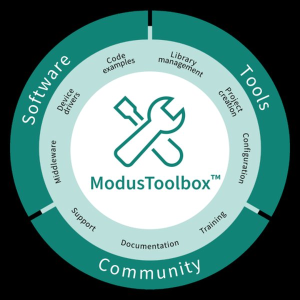
Overview of the ModusToolbox software environment.
System Requirements
Ensure your system meets the following criteria:
- Operating System: Windows, Linux, or macOS (check the latest ModusToolbox documentation for supported versions).
- Development Board: A compatible Infineon development board (e.g., PSoC 6 or XMC7000 series) with a debugging interface (KitProg3, MiniProg4).
Software Dependencies
The following software components are crucial:
- ModusToolbox™ Software: Download and install the latest version from the Infineon website. The setup program can install the base packages, Eclipse IDE, compilers, and middleware. It's recommended to log in with your Infineon account during setup for access to all resources.
- Eclipse IDE for Embedded C/C++ Developers: ModusToolbox often bundles a version of Eclipse. If not, or if you prefer a specific version, download the Eclipse Installer from the Eclipse downloads page and select the "Eclipse IDE for Embedded C/C++ Developers" package.
- Python: Version 3.7 or later is typically required for various scripts and tools used with MCUboot (e.g.,
imgtool, CySecureTools). Ensure Python is installed and added to your system's PATH. - Git: Essential for cloning MCUboot example repositories and managing version control. Download from git-scm.com if not already installed.
- Arm GNU Toolchain: Necessary for compiling code for Arm Cortex-M based MCUs. ModusToolbox setup usually handles this, or it can be installed separately.
- CMake (Optional): Some projects or build configurations might require CMake.
Step-by-Step Installation and Configuration
Follow these detailed steps to integrate MCUboot into your Eclipse IDE for ModusToolbox environment.
Step 1: Install ModusToolbox™ and Eclipse IDE
Download and Install ModusToolbox™
Visit the Infineon ModusToolbox page to download the installer for your operating system. Run the setup program, which will guide you through installing the core tools, the optional Eclipse IDE, and relevant libraries. During installation, ensure you select packages related to your target MCU and any secure bootloader libraries if explicitly listed.
Verify Eclipse IDE Setup
Once ModusToolbox is installed, launch the Eclipse IDE provided (usually found in the tools_ide/eclipse subdirectory of your ModusToolbox installation). If you installed Eclipse separately, ensure it's the "Eclipse IDE for Embedded C/C++ Developers" version. The ModusToolbox environment should automatically configure Eclipse with necessary plugins and paths. You may need to point Eclipse to the SEGGER J-Link path if you use J-Link debug probes (Window > Preferences > MCU > Global SEGGER J-Link Path).
Step 2: Obtain the MCUboot Project
Clone an Example Project
Infineon provides example projects that serve as excellent starting points. The recommended approach is to clone an official MCUboot example repository for PSoC 6 or your target MCU. A common example is mtb-example-mcuboot-basic:
git clone https://github.com/Infineon/mtb-example-mcuboot-basic.gitAlternatively, you can use mtb-example-psoc6-mcuboot-basic if you are specifically targeting PSoC 6.
git clone https://github.com/Infineon/mtb-example-psoc6-mcuboot-basic.gitThese repositories contain the MCUboot source code, example applications, and the necessary ModusToolbox project structure.
Step 3: Import the MCUboot Project into Eclipse IDE
With the project files downloaded, import them into your Eclipse workspace:
- Open Eclipse IDE for ModusToolbox.
- Navigate to File > Import....
- Expand the ModusToolbox category and select Existing ModusToolbox Project into Workspace. If this option is not available, you can use General > Existing Projects into Workspace.
- Click Next. For "Select root directory," browse to the folder where you cloned the MCUboot example project (e.g.,
mtb-example-mcuboot-basic). - Ensure the project is selected in the "Projects" list.
- Check "Copy projects into workspace" if you prefer to work with a copy within your Eclipse workspace directory.
- Click Finish.
Eclipse will import the project and attempt to resolve its dependencies using the ModusToolbox Library Manager.
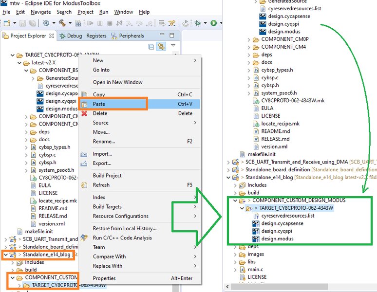
Example of an imported project in the Eclipse IDE Project Explorer.
Step 4: Install and Configure Dependencies
MCUboot relies on several components, including cryptographic libraries and image management tools.
ModusToolbox Library Manager
Many dependencies are managed through the ModusToolbox Library Manager, accessible within Eclipse (often by right-clicking the project). Ensure that libraries like `MCUboot` core, `CySecureTools` (for signing and potentially encryption), and any necessary cryptographic libraries (e.g., mbedTLS, or platform-specific hardware crypto drivers) are present and up-to-date. The example project should already define these in its `*.lib` file or equivalent manifest.
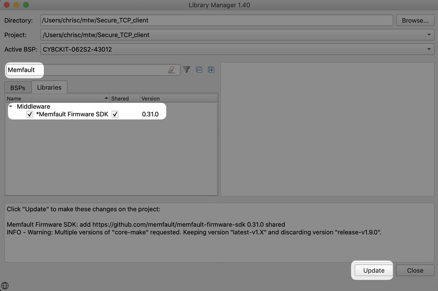
Using the ModusToolbox Library Manager to manage project dependencies.
Install `imgtool` Dependencies
MCUboot uses a Python script called `imgtool` for signing firmware images. Some example projects include a script to install its dependencies. Navigate to the scripts directory within the MCUboot library folder (e.g., `<mtb_shared>/mcuboot/<tag>/scripts` or a similar path within your project's `deps` folder) and run:
python install_dependencies.pyOn Linux/macOS, you might need to use `python3`.
Step 5: Configure Project Settings
Fine-tune the project configuration for your specific needs:
- Flash Memory Layout: MCUboot relies on a defined flash layout. This is typically specified in JSON files located in a `flashmap/` directory within the project. These files define primary and secondary image slots, scratch areas, etc. Ensure these are appropriate for your target hardware.
- Signing Keys: Secure boot requires cryptographic keys for signing firmware images. Example projects often include sample keys in a `keys/` directory (e.g., `.pem` files). For production, you must generate and protect your own unique keys.
- Build Configuration: Verify the Makefile or build scripts. For MCUs like PSoC 6, the bootloader (MCUboot) typically runs on one core (e.g., CM0+), while the main application runs on another (e.g., CM4). Ensure the build targets are set correctly.
- Target Board and Debugger: In Eclipse project properties (Right-click project > Properties), confirm that the target board and debugger settings (e.g., KitProg3) are correctly configured for your hardware setup.
Step 6: Build and Flash the MCUboot Project
Build the Project
Once configured, build the MCUboot project:
- In Eclipse, select the project in the Project Explorer.
- Right-click the project and select Build Project, or use the hammer icon in the toolbar.
- The build process will compile the bootloader and, if included in the example, a sample application. Monitor the Console view in Eclipse for build logs and ensure there are no errors. The output typically includes `.hex` or `.elf` files for the bootloader and application.
Flash the Bootloader and Application
After a successful build:
- Connect your development board to your computer via USB (ensure the debugger, like KitProg3, is connected).
- In Eclipse, create or select a Debug Configuration (Run > Debug Configurations...). Choose the appropriate configuration for your target MCU and debug probe.
- Launch the debug session. This will typically flash the compiled bootloader (and application, if configured) onto the target device.
- Alternatively, use the ModusToolbox programming utilities or the Eclipse "Flash" commands if available for your project configuration.
After flashing, reset the board. The MCUboot bootloader should execute first, verify the application image, and then jump to it. You can monitor this process via a serial terminal connected to the board's UART output if the bootloader or application includes logging.
Visualizing the Development Workflow
The following mindmap illustrates the key stages involved in setting up an MCUboot project within the Eclipse IDE for ModusToolbox. It provides a high-level overview of the entire process, from initial preparations to building and flashing the project.
(e.g., mtb-example-mcuboot-basic)"] id2_3["Import Project into Eclipse"] id3["Configuration"] id3_1["Manage Dependencies
(Library Manager, imgtool scripts)"] id3_2["Configure Flash Map (JSON files)"] id3_3["Set Up Signing Keys (.pem files)"] id3_4["Adjust Build Settings (Makefile, Target Cores)"] id3_5["Verify Debugger Configuration"] id4["Build & Deploy"] id4_1["Build Project in Eclipse"] id4_2["Flash Bootloader to Target"] id4_3["Flash Application Image"] id4_4["Test & Debug"] id5["MCUboot Core Concepts"] id5_1["Secure Boot"] id5_2["Firmware Update (OTA/Serial)"] id5_3["Image Slots (Primary, Secondary)"] id5_4["Image Signing & Verification"]
This mindmap helps in understanding the flow and interdependencies of different tasks, ensuring a structured approach to your MCUboot integration.
Understanding MCUboot's Flash Layout
MCUboot's operation heavily relies on a well-defined flash memory layout. This layout dictates where the bootloader itself resides, where the primary application image is stored, where an updated image (secondary slot) can be placed, and potentially a scratch area for swap operations during updates. The video below provides a concise overview of this flash layout, which is critical for configuring your `flashmap.json` files correctly.
Understanding these concepts is vital for successful firmware updates and ensuring the bootloader can correctly identify and validate images. The primary slot holds the currently running application, while the secondary slot is used to store a new firmware image before it's validated and swapped (or booted directly in some modes).
Key Configuration Files and Their Roles
Several files play crucial roles in configuring and building an MCUboot project within ModusToolbox. Understanding their purpose is essential for customization and troubleshooting.
| File/Directory | Purpose | Typical Location |
|---|---|---|
Makefile |
Contains build rules, compiler flags, linker settings, and targets for compiling the bootloader and application. Defines how different components are built and linked. | Project root, or specific application/bootloader directories. |
flashmap/*.json |
JSON files defining the flash memory layout for MCUboot. Specifies regions for the bootloader, primary image slot, secondary image slot, and scratch area. | flashmap/ directory or similar within the project structure. |
keys/*.pem |
Cryptographic keys (private and public) used for signing firmware images. The private key signs the image, and the public key (embedded in the bootloader) verifies the signature. | keys/ directory or as specified by build scripts. |
*.lib file (e.g., design.modus or project manifest) |
ModusToolbox file listing project dependencies (libraries, middleware like MCUboot, BSPs). Used by the Library Manager. | Project root. |
deps/ |
Directory containing the source code or links to project dependencies, including MCUboot core files, cryptographic libraries, and Hardware Abstraction Layers (HAL). | Project root. |
scripts/install_dependencies.py (or similar) |
Python script often provided with MCUboot or related tools (like `imgtool`) to install necessary Python packages required for image processing, signing, etc. | Within the MCUboot library (e.g., deps/mcuboot/scripts/) or a tools directory. |
Project Configuration Files (e.g., .cproject, .project) |
Eclipse IDE specific files that store project settings, build configurations, include paths, and other IDE-related metadata. | Project root (hidden by default in some views). |
Familiarity with these files will allow you to adapt the MCUboot project to your specific hardware and security requirements effectively.
Comparing Development Aspects with MCUboot
Developing with a secure bootloader like MCUboot involves various considerations. The radar chart below provides a qualitative comparison of different aspects of the development lifecycle when incorporating MCUboot into a ModusToolbox project via Eclipse, contrasted with a hypothetical, simpler (but less secure/featured) bootloader scenario. The scores are on a scale of 1 (Less Favorable/More Complex) to 10 (More Favorable/Simpler), where "favorable" means easier or more efficient from a developer's perspective for that specific aspect.
This chart highlights that while MCUboot offers superior security and update robustness, it may involve a slightly steeper learning curve and more complex initial setup compared to very basic bootloaders. However, the ModusToolbox environment and example projects significantly aid in managing this complexity.
Frequently Asked Questions (FAQ)
What is MCUboot?
MCUboot is an open-source, secure bootloader designed for 32-bit microcontrollers. Its primary functions are to verify the integrity and authenticity of firmware images before execution and to manage secure firmware updates. It is OS-agnostic and relies on hardware porting layers for specific MCUs.
Why use MCUboot with ModusToolbox?
ModusToolbox provides an integrated development environment for Infineon MCUs. Using MCUboot within this ecosystem allows developers to leverage robust secure boot and firmware update capabilities for their applications, supported by Infineon's tools, examples, and libraries. This simplifies the development of secure IoT devices and other embedded systems.
What are common challenges during MCUboot setup?
Common challenges include:
- Incorrect Python environment setup or missing dependencies for tools like `imgtool`.
- Misconfiguration of the flash memory map (`flashmap.json`).
- Issues with cryptographic key generation, management, or an incorrect public key embedded in the bootloader.
- Toolchain or compiler compatibility problems.
- Incorrectly configured project dependencies in ModusToolbox.
Starting with an official example project usually helps mitigate many of these issues.
Where can I find example MCUboot projects for ModusToolbox?
Infineon provides example projects on GitHub. A good starting point is the mtb-example-mcuboot-basic repository or similar ones specific to PSoC 6 like mtb-example-psoc6-mcuboot-basic. These examples come pre-configured for ModusToolbox and Eclipse.
What are `imgtool` or `CySecureTools` used for?
`imgtool` is a Python script used by MCUboot to perform operations on firmware images, such as signing them with a private key, adding headers, and verifying image integrity. `CySecureTools` is a suite of tools from Infineon that may include similar functionalities, often more tightly integrated with their PSoC MCUs, for secure image generation, key management, and provisioning for secure boot and secure firmware updates.
Recommended Next Steps
To deepen your understanding and explore further, consider these related topics:
- Learn how to generate and manage cryptographic signing keys for secure firmware with MCUboot.
- Explore advanced flash layout configurations for dual-core MCUs like PSoC 6 with MCUboot.
- Discover how to implement Over-the-Air (OTA) firmware updates using MCUboot in a ModusToolbox project.
- Find out techniques for debugging both the MCUboot bootloader and the main application code in a single Eclipse session.
References
 static4.arrow.com
static4.arrow.com
static4.arrow.com
Last updated May 16, 2025