
Configuring LabVIEW for SPI Communication
A comprehensive guide to setting up SPI in LabVIEW
LabVIEW offers robust tools and APIs to facilitate Serial Peripheral Interface (SPI) communication, providing a flexible environment for handling data transfer with various SPI-compatible devices. In this detailed guide, we will cover the steps required to configure LabVIEW for SPI, the hardware and software prerequisites, details on using both the Basic and Advanced APIs, and suggestions for troubleshooting and testing your configuration.
Essential Highlights
- Complete Hardware and Software Setup: Understand the necessary hardware connections and install all required software components including LabVIEW, NI VISA, and LabVIEW MakerHub LINX.
- Configuring SPI Parameters: Learn how to set up SPI settings such as clock frequency, clock polarity, phase, and chip select options using LabVIEW’s SPI Configuration nodes.
- Implementation and Testing: Gain insights on programming using SPI VIs; deploy configuration, script transactions if needed, and test using LabVIEW’s integrated tools.
Understanding SPI and LabVIEW Integration
SPI Fundamentals
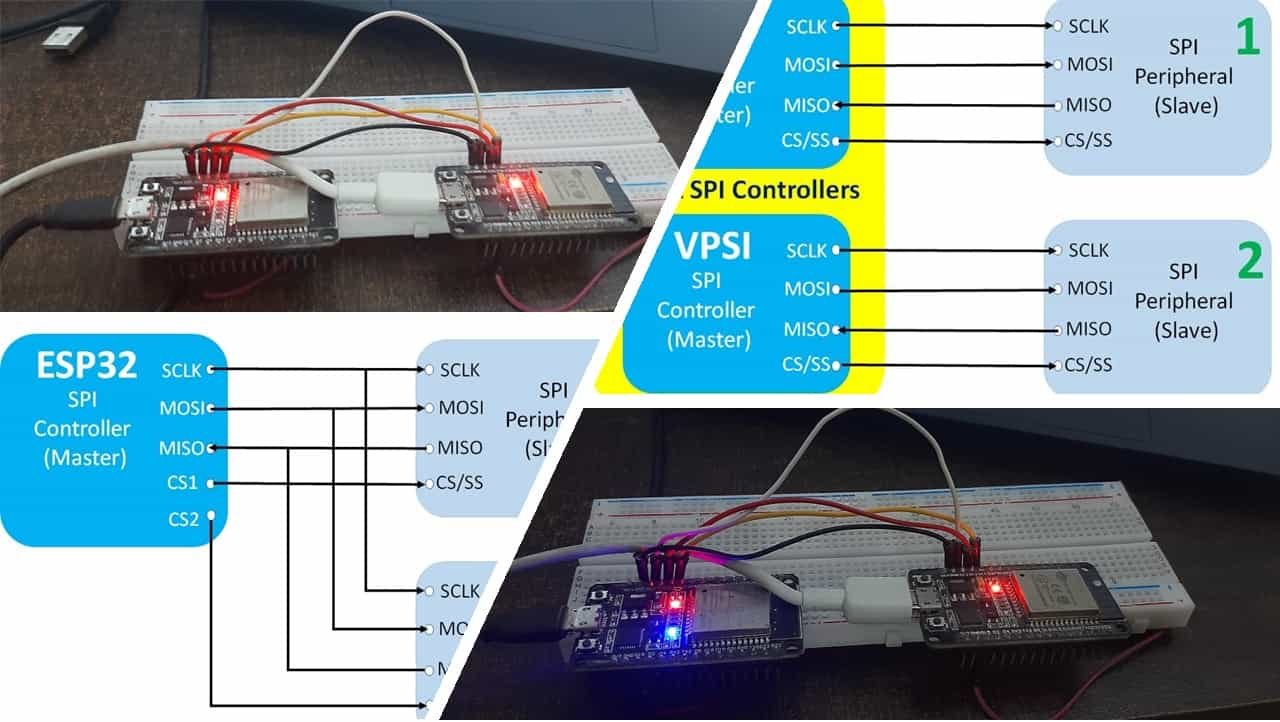
Serial Peripheral Interface (SPI) is a synchronous serial communication protocol primarily used to transfer data between a microcontroller (or master device) and one or more peripherals (slave devices). SPI communication typically involves the following four connections:
- SCLK (Serial Clock): Generated by the master device to synchronize data transfer.
- MOSI (Master Out Slave In): Used for data transmission from the master to the slave.
- MISO (Master In Slave Out): Used for data reception from the slave to the master.
- CS (Chip Select): Also known as NSS (Negative Slave Select), it is used to select the specific slave device involved in the current communication.
Understanding these connections is paramount. The synchronization provided by the clock (SCLK) and the directional flow of data through MOSI and MISO form the backbone of any SPI system. This standard makes SPI a prevalent choice for interfacing with sensors, memory devices, and other peripheral components.
LabVIEW and SPI Integration
LabVIEW, with its graphical programming approach, offers specialized tools and APIs that facilitate SPI communication. Depending on the complexity of your application, you can opt for either the SPI Basic API or the SPI Advanced API:
- SPI Basic API: Designed for straightforward SPI communications. It provides configuration VIs to set basic parameters like clock frequency, phase, polarity, and chip select settings. This approach is generally sufficient for most applications.
- SPI Advanced API: Caters to more complex communication scenarios. It allows you to create detailed scripts that define how the master and slave devices interact, managing chip select addressing and custom data transactions. This approach provides extra flexibility for advanced applications.
Step-by-Step Configuration of SPI in LabVIEW
Step 1: Requirements and Setup
Hardware Requirements
Before configuring LabVIEW for SPI, ensure that you have the following hardware components:
- A LabVIEW-compatible DAQ device or interface (e.g., NI USB-8451) that can support SPI communication.
- An SPI peripheral device (e.g., temperature sensor, accelerometer, or display module such as ADXL345 or PmodALS).
- Optional microcontroller for bridging the connection, if required for specific setups.
Software Requirements
To get started, you will need the following software components installed on your system:
- LabVIEW: Install the latest version of LabVIEW, noting that even a Home Bundle or free trial version may suffice.
- NI VISA: A driver package essential for communication between LabVIEW and SI-compatible hardware.
- LabVIEW MakerHub LINX: This toolkit simplifies communication with external devices using SPI and other protocols. It includes sample VIs and comprehensive documentation.
Step 2: Hardware Connection and Deployment
Connecting the SPI Device
Follow these guidelines to properly connect your hardware:
- SCLK: Connect the clock line generated by the master (LabVIEW or accompanying microcontroller) to the SPI peripheral device.
- MOSI: Wire the MOSI pin from the master to the input of the slave device so that data can be sent correctly.
- MISO: Connect the MISO pin from the slave back to the master’s receiving pin to capture data transmitted by the peripheral.
- CS: Integrate the Chip Select line with an appropriate digital output. The CS can be active high or low depending on your SPI device’s requirements – refer to the datasheet for correct configuration.
If you are using a microcontroller in your setup, ensure that the device drivers are installed and that the microcontroller is properly connected via USB. Use LabVIEW MakerHub LINX’s Firmware Wizard to deploy the necessary firmware onto the microcontroller, which will handle the SPI communication as dictated by your configuration.
Step 3: Configuring LabVIEW for SPI Communication
Using the SPI Basic API
For most applications, the SPI Basic API is sufficient. Follow these steps to configure it:
- Create a SPI Configuration: Open LabVIEW and add the SPI Configuration VI from the palette. This VI is designed to initialize a SPI configuration that includes parameters like clock frequency, phase, polarity, and chip select properties.
- Set the Communication Parameters: Specify:
- Clock Rate: Determine the speed at which data will be transmitted. Higher speeds may require careful signal integrity analysis.
- Clock Polarity and Phase: Set these according to the specifications of your SPI device. These parameters determine how data is sampled relative to the clock signal.
- Chip Select (CS) Addressing: Define the method for handling the CS line. You may need to adjust for whether the chip select is active high or active low.
- Creating a Reference: Once configured, the SPI configuration VI will produce a reference that can be attached to subsequent SPI Write/Read VIs for data transaction.
This form of configuration ensures that LabVIEW commands can correctly manage SPI communications, facilitating both writing to and reading from your peripheral device.
Using the SPI Advanced API
For more advanced implementations, use the SPI Advanced API. This approach is ideal when you need to create custom SPI transactions or handle multiple devices with varying configurations. Follow these steps:
- Create an SPI Script: Use scripting functions to outline detailed rules for communication, including initial commands, data timing, and chip select toggling.
- Detailed Control: The advanced API allows granular control over each signal line. Modify settings on the fly, adjust scripts for customized transactions, and manage multiple phases of data transfer within a single VI.
- Integration with LINX: When working with LabVIEW MakerHub LINX, locate the relevant SPI Advanced API functions provided to integrate smoothly with external microcontrollers.
Step 4: Building Your LabVIEW VI for SPI Communication
Creating the Front Panel and Block Diagram
Once your hardware connections and configuration settings are ready, build your Virtual Instrument (VI) in LabVIEW as follows:
- Front Panel Controls: Include controls for setting the clock frequency, selecting chip select parameters, and executing send/receive commands. You might also want to add indicators to display received data.
- Block Diagram Implementation:
- Place the SPI Configuration VI early in your block diagram to generate and store the SPI reference.
- Integrate a loop structure (often a while loop) with an event structure to handle user inputs like send/stop commands. This approach provides flexibility in sending and receiving data on demand.
- Add the SPI Write and SPI Read VIs that use the earlier configuration. Connect these appropriately so that data transactions are managed according to your configured parameters.
- Error Handling: Always include error handling routines within your VI to capture any discrepancies in communication. This will provide insights during troubleshooting and ensure safe recovery from unexpected conditions.
Step 5: Testing and Troubleshooting
Testing Your SPI Configuration
After you've built your VI, it’s crucial to test the SPI communication to ensure that the system works as expected:
- Run the VI: Execute your VI and monitor the behavior of the SPI signals. Utilize LabVIEW's built-in tools to observe data on the front panel.
- Use External Tools: An oscilloscope or logic analyzer can help validate the correct timing, polarity, and phase of the SPI signals (MOSI, MISO, SCLK, CS). This hardware verification is a key step when troubleshooting.
- Analyze Data Flow: Verify that data is being correctly transmitted and received. Compare the results with the expected behaviors specified in your device’s datasheet.
Troubleshooting Common Issues
If you encounter problems during communication:
- Pin Configuration: Double-check that the wiring between the master and slave is correct. Ensure there is no misconfiguration of the MOSI, MISO, SCLK, or CS pins.
- SPI Settings Mismatch: Verify that you have accurately set the clock frequency, polarity, and phase as required by your peripheral device. Even small mismatches can result in communication errors.
- Error Messages: Pay attention to LabVIEW’s error messages. Implement comprehensive error handling in your VI to provide detailed feedback on the nature of any faults.
- Software Conflicts: Ensure that no other application (such as WaveForms or conflicting tools) is interfacing with your LabVIEW session. Close unnecessary applications if conflict arises.
Comprehensive SPI Configuration Workflow
The table below summarizes the workflow for a typical SPI configuration in LabVIEW:
| Step | Actions | Tools/Settings |
|---|---|---|
| Hardware Setup | Connect SCLK, MOSI, MISO, CS between master and SPI device | NI USB-8451, Microcontroller (if needed) |
| Install Software | Install LabVIEW, NI VISA, LINX Toolkit | LabVIEW MakerHub LINX, NI-VISA libraries |
| SPI Configuration | Create and configure SPI reference | Set clock frequency, polarity, phase, chip select specifics |
| VI Construction | Build front panel, insert SPI Write/Read VIs and error handling | Front Panel Controls, While Loop with Event Structure |
| Testing & Troubleshooting | Execute VI, monitor signals, adjust settings based on analysis | Oscilloscope/Logic Analyzer, LabVIEW Error Outputs |
Additional Considerations and Best Practices
Using LabVIEW FPGA
If you require high-speed or deterministic control over the SPI communication, consider deploying LabVIEW FPGA. With LabVIEW FPGA, you can implement a state machine using Single-Cycle Timed Loops (SCTL) that efficiently manage the SPI protocol. This is particularly useful when dealing with multiple peripherals or when precise timing is paramount.
Integrating with LINX
LabVIEW MakerHub LINX simplifies SPI communication when interfacing with microcontrollers. LINX includes VIs specifically for configuring and managing SPI channels. Once the microcontroller is set up with the appropriate firmware, these VIs can quickly establish communication between the PC and the SPI peripheral. This toolkit is especially useful for hybrid applications that mix PC-based processing with embedded control.
Handling Data Transactions
Create VIs to seamlessly handle bidirectional data transmission. Use SPI Write VIs to send commands or configuration data, and SPI Read VIs to capture responses from your peripheral. Encapsulate the entire transaction within a loop that monitors for errors and reacts to user input. This approach ensures a robust implementation where the system can gracefully recover from any transient communication errors.
References
- Using SPI with LabVIEW and the USB-8451 - NI
- SPI in LabVIEW Using MakerHub LINX - Instructables
- Understanding the SPI Bus with NI LabVIEW - NI
- Implementing SPI Communication Protocol in LabVIEW FPGA - NI Forums
- LabVIEW SPI Configure - MakerHub LINX
Recommended Queries for Further Research
Last updated March 17, 2025