
Connecting Devices through UART in LabVIEW
A Comprehensive Guide to UART Communication with LabVIEW
Key Takeaways
- Essential Setup: Proper hardware connections and software installations are critical for successful UART communication.
- Configuration Parameters: Accurate configuration of baud rate, data bits, parity, stop bits, and flow control ensures reliable data transfer.
- Error Handling: Implementing robust error checking and debugging techniques is vital for maintaining stable communication.
1. Introduction to UART Communication in LabVIEW
Universal Asynchronous Receiver/Transmitter (UART) is a widely used protocol for serial communication between devices. LabVIEW, a system-design platform and development environment from National Instruments, provides comprehensive tools to facilitate UART communication. This guide walks you through the process of connecting a device via a UART port using LabVIEW, ensuring a seamless and efficient setup.
2. Hardware Setup
2.1 Identifying UART Pins
Before establishing communication, it's essential to identify the UART pins on both the device and the computer/interface. Typically, UART connections include:
- TX (Transmit): Sends data from the device.
- RX (Receive): Receives data to the device.
- GND (Ground): Common ground reference between devices.
- Optional: RTS (Ready to Send) and CTS (Clear to Send) for flow control.
2.2 Connecting the Hardware
-
Using a USB-to-UART Converter:
If your computer lacks a native UART port, a USB-to-UART converter (e.g., FTDI, Silicon Labs CP210x) is necessary.
- Connect the TX pin of the device to the RX pin of the converter.
- Connect the RX pin of the device to the TX pin of the converter.
- Connect the GND pins of both devices to establish a common ground.
- If necessary, connect RTS and CTS or leave them grounded/floating based on application requirements.
-
Power Supply Considerations:
Ensure that both devices are adequately powered. Some UART connections might require separate power sources.
2.3 Verifying Connections
After establishing the physical connections, verify them using a multimeter to ensure continuity and correct pairing of TX and RX lines.
3. Software Setup
3.1 Installing LabVIEW
Ensure that the latest version of LabVIEW is installed on your computer. You can download it from the National Instruments website.
3.2 Installing Necessary Drivers
-
NI-VISA:
National Instruments Virtual Instrument Software Architecture (NI-VISA) is essential for serial communication. Download and install it from the NI website.
-
USB-to-UART Bridge Drivers:
Depending on your converter, install the appropriate drivers:
- FTDI VCP Drivers: For FTDI-based converters. Available at the FTDI website.
- Silicon Labs CP210x Drivers: For CP210x-based converters. Available at the Silicon Labs website.
-
LINX Toolkit (Optional):
If interfacing with microcontrollers like Arduino or Raspberry Pi, install the LINX toolkit from the NI GitHub repository to provide additional communication tools.
3.3 Configuring the COM Port
-
Using Device Manager (Windows):
After connecting the USB-to-UART converter, open the Device Manager:
- Press Win + X and select Device Manager.
- Expand the Ports (COM & LPT) section to identify the assigned COM port (e.g., COM3).
-
Using NI Measurement & Automation Explorer (NI-MAX):
Launch NI-MAX to view connected devices:
- Open NI-MAX from the Start menu.
- Navigate to Devices and Interfaces to identify the COM port associated with the UART connection.
4. Configuring UART Communication in LabVIEW
4.1 Setting Up a New Virtual Instrument (VI)
- Launch LabVIEW.
- Create a new VI by selecting File > New VI.
4.2 Designing the Block Diagram
The Block Diagram is where you'll program the UART communication logic.
4.2.1 Adding VISA Configure Serial Port VI
- Open the Functions Palette by right-clicking on the Block Diagram.
- Navigate to Instrument I/O > Serial.
- Drag and drop the VISA Configure Serial Port VI onto the Block Diagram.
- Configure the following parameters:
- VISA Resource Name: Specify the COM port (e.g., COM3).
- Baud Rate: Set according to your device's specifications (commonly 9600 or 115200).
- Data Bits: Typically set to 8.
- Parity: Set to None, Even, or Odd as required.
- Stop Bits: Usually set to 1.
- Flow Control: Set to None, RTS/CTS, or XON/XOFF based on device requirements.
4.2.2 Writing Data to the UART
- Add the VISA Write VI from the Serial palette.
- Connect the VISA Resource Name from the VISA Configure Serial Port VI to the VISA Write VI.
- Provide the data you wish to send:
- Add a String Control on the Front Panel to input data.
- Connect it to the Write Buffer input of the VISA Write VI.
4.2.3 Reading Data from the UART
- Add the VISA Read VI from the Serial palette.
- Connect the VISA Resource Name from the previous VIs to the VISA Read VI.
- Specify the number of bytes to read or use a termination character:
- Add a Numeric Control to set the number of bytes.
- Connect it to the Byte Count input of the VISA Read VI.
- Add a String Indicator on the Front Panel to display received data.
- Connect it to the Read Buffer output of the VISA Read VI.
4.2.4 Closing the Serial Port
- Add the VISA Close VI from the Serial palette.
- Connect the VISA Resource Name through all the VIs to the VISA Close VI.
4.2.5 Implementing Error Handling
- Add an error cluster to manage and debug errors:
- Use the Merge Errors VI to consolidate error information.
- Connect the Error In and Error Out clusters accordingly.
- Implement a Case Structure to handle errors dynamically.
4.3 Designing the Front Panel
The Front Panel serves as the user interface for your VI.
- Add controls and indicators corresponding to the Block Diagram elements:
- String Control: Input data to send via UART.
- Numeric Control: Set the number of bytes to read.
- String Indicator: Display received data.
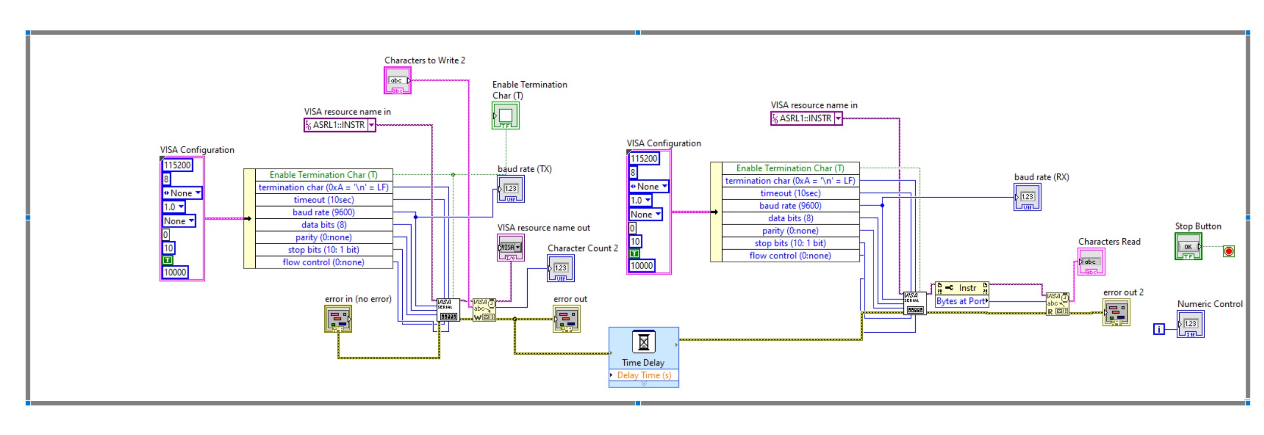
5. Example LabVIEW Block Diagram
The following table outlines a basic structure of the LabVIEW Block Diagram for UART communication:
| Step | VI Component | Configuration |
|---|---|---|
| 1 | VISA Configure Serial Port | Set COM port, baud rate, data bits, parity, stop bits, flow control. |
| 2 | VISA Write | Send data entered in the String Control. |
| 3 | VISA Read | Read specified number of bytes and display in String Indicator. |
| 4 | VISA Close | Close the serial port after communication. |
| 5 | Error Handling | Manage and display errors using Case Structures. |
Additionally, incorporating a While Loop can facilitate continuous communication:
// Block Diagram Structure
VISA Configure Serial Port → While Loop →
    (VISA Write → VISA Read) →
VISA Close
This structure ensures that data is continuously read and written until the loop is terminated.
6. Testing and Debugging
6.1 Running the VI
After setting up the Block Diagram and Front Panel, run the VI by clicking the Run button. Monitor the communication by observing the String Indicator for incoming data.
6.2 Error Checking
- Ensure that the error clusters are correctly displaying error statuses.
- Use LabVIEW’s built-in debugging tools:
- Breakpoints: Set breakpoints to pause execution and inspect data.
- Probe Tool: Monitor wire values during execution.
6.3 Verifying Data Integrity
Confirm that the data sent from LabVIEW matches the data received by the device and vice versa. Use checksums or other data validation methods if necessary.
6.4 Troubleshooting Common Issues
-
Incorrect Wiring:
Double-check the TX and RX connections. Ensure that TX from one device is connected to RX on the other and vice versa.
-
Mismatched Configuration:
Verify that the baud rate, data bits, parity, stop bits, and flow control settings match between LabVIEW and the connected device.
-
COM Port Conflicts:
Ensure that no other application is using the same COM port. Close any conflicting applications.
-
Driver Issues:
Reinstall or update the USB-to-UART converter drivers if communication fails.
7. Advanced Topics
7.1 Utilizing LINX Toolkit for Microcontrollers
The LINX toolkit extends LabVIEW’s capabilities to interface with various microcontrollers. To use LINX for UART communication:
- Install the LINX toolkit from the NI GitHub repository.
- Configure the microcontroller with LINX firmware.
- Use LINX-specific VIs like LINX UART Open and LINX UART Close for managing connections.
7.2 Implementing Flow Control
Flow control manages the rate of data transmission between devices to prevent data loss. Common flow control methods include:
- None: No flow control; assumes both devices can handle the data rate.
- RTS/CTS (Hardware Flow Control): Uses RTS and CTS lines to control data flow.
- XON/XOFF (Software Flow Control): Uses specific control characters to manage data flow.
Configure flow control settings in both LabVIEW and the connected device to ensure synchronized communication.
7.3 Enhancing Data Integrity
To ensure reliable data transfer:
- Implement checksums or CRC (Cyclic Redundancy Check) in your data packets.
- Use acknowledgments (ACK/NACK) to confirm successful data reception.
- Employ timeouts and retries for critical communications.
8. Example Applications
8.1 Connecting to Microcontrollers
UART communication is commonly used to interface LabVIEW with microcontrollers such as Arduino, STM32, or Raspberry Pi:
-
Data Acquisition: Collect sensor data from microcontrollers.
-
Control Systems: Send control commands to actuators or other peripherals.
-
Firmware Updates: Upload new firmware or configurations.
8.2 Interfacing with Sensor Modules
Many sensors communicate via UART. Using LabVIEW to interface with these sensors allows for real-time data monitoring and analysis.
8.3 Industrial Applications
UART is prevalent in industrial settings for connecting various devices like PLCs, HMI panels, and other instrumentation equipment. LabVIEW can facilitate robust communication and data exchange in such environments.
9. Conclusion
Establishing UART communication between LabVIEW and external devices involves meticulous hardware setup, precise software configuration, and robust error handling. By following this comprehensive guide, you can effectively leverage LabVIEW's powerful tools to facilitate reliable serial communication, enabling a wide range of applications from data acquisition to device control. Always ensure that hardware connections are secure, configurations are accurately set, and thorough testing is conducted to maintain stable communication channels.
10. References
Last updated January 24, 2025