
Limpet Jacket Area Calculation for Reactor with Head
Comprehensive guide for calculating and optimizing heat transfer area
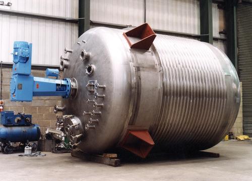
Highlights
- Integrated Approach: Combining shell and head contributions to overall heat transfer area.
- Dimensional Analysis: Use reactor dimensions, coil geometry, and pitch to compute effective area.
- Practical Considerations: Adjustments for operating conditions, coil layout, and contact efficiency.
Introduction to Limpet Jacket Design
A limpet jacket is an external heat transfer system, often comprising half-pipe coils that are welded onto a reactor vessel. When a reactor has a head (typically a torispherical or hemispherical end), it is essential to factor in both the cylindrical shell and the head's contribution when calculating the total heat transfer area. This comprehensive guide explains how to determine the limpet jacket area, incorporating reactor dimensions, coil geometry, and practical challenges encountered in design and operation.
Understanding the Limpet Jacket Configuration
In reactors utilizing limpet jackets, half-pipe coils are arranged along the cylindrical shell and can also be extended over the head. The effective heat transfer area is not just the geometric surface area of the reactor but rather the surface area of the coil that is in contact with the vessel wall. In many cases, due to gaps between coil turns and limitations in coil contact, the effective heat transfer area is only about 60-65% of the total outer surface area covered by the jacket. The coils can also be designed with enhanced configurations to promote turbulence and improve efficiency.
Coil Arrangement and Geometry
The arrangement of the limpet coil is critical for both thermal performance and structural feasibility. Two pivotal areas are considered: the shell (or cylindrical section) and the head (the domed or torispherical end). Each portion requires separate evaluation:
Cylindrical Shell
The exterior of the reactor shell dictates the length of the coil required. The basic formula to calculate the lateral area of a cylinder is:
\( \text{Area}_{\text{cylinder}} = \pi \times D \times H \) where \( D \) is the outer diameter of the reactor and \( H \) is its height.
While this formula gives the overall surface area, the limpet coil only covers a fraction of this surface, usually optimized through the coil’s layout. Adjustments are made to account for gaps between turns and the effective area of contact.
Head (Dish End) Contribution
The reactor head can have different geometries (hemispherical, torispherical, etc.). For a hemispherical head, the effective heat transfer area is commonly approximated by:
\( \text{Area}_{\text{head}} = \frac{1}{2} \times \pi \times D^2 \)
In many practical applications, the head’s contribution is represented as a percentage (around 11%) of the cylinder’s area, particularly for torispherical heads. This simplification aids in integrating the two areas when calculating the overall heat transfer capacity.
Calculations for Limpet Coil Jacket Area
The total limpet jacket area is calculated by separately determining the contributions from the cylindrical shell and the head, and then combining them. The process is as follows:
Step 1: Determine Reactor Dimensions
Measure the following key dimensions:
- Outer diameter of the reactor (typically after adding wall thickness).
- Height of the cylindrical section where the coil is applied.
- Dimensions of the reactor head (diameter and curvature characteristics such as torispherical or hemispherical).
Step 2: Calculate Cylindrical Shell Area
While the geometric surface area is calculated using the formula:
\( \text{Area}_{\text{cylinder}} = \pi \times D \times H \)
The actual effective heat transfer area is reduced by the coverage efficiency of the limpet coil. Typically, only about 60-65% of the calculated geometric area contributes effectively. Thus, if the coil covers only a portion of the surface or includes spacing, an adjustment factor is applied.
Step 3: Calculate Head Area
For a hemispherical head, use:
\( \text{Area}_{\text{head}} = \frac{1}{2} \times \pi \times D^2 \)
For torispherical heads, the contribution is often estimated to be roughly 11% of the cylindrical heat transfer area. This is a practical approximation aimed at simplifying head area calculations in complex geometries.
Step 4: Determine Limpet Coil Parameters
Next, examine the specific coil configuration:
- Coil Length per Turn: Calculate using \( L_1 = \frac{D_{Lo} \times \pi}{1000} \), where \( D_{Lo} \) is the outer diameter of the limpet coil jacket. This incorporates the reactor diameter, additional clearance, and the pipe’s outer diameter.
- Number of Turns: Determine by dividing the limpet coil height by the pitch (the distance between successive coil turns).
- Total Coil Length: Multiply the length per turn by the number of turns: \( L_{\text{total}} = L_1 \times \#T \).
- Effective Heat Transfer Area per Turn: Given by the formula \( A_{\text{turn}} = \pi \times d_o \times L_1 \), where \( d_o \) is the outer diameter of the limpet coil pipe. Multiply by the number of turns to approximate the total coil area.
Step 5: Integrate Both Areas
To obtain the overall limpet jacket heat transfer area, sum the effective areas from the cylindrical section and the head. Formally, the total effective area \( A_{\text{total}} \) is expressed as:
\( A_{\text{total}} = A_{\text{cylinder, effective}} + A_{\text{head, effective}} \)
where \( A_{\text{cylinder, effective}} \) is the product of the geometric cylinder area and the efficiency factor (60-65%), and \( A_{\text{head, effective}} \) is calculated based on the head’s geometry.
Practical Example and Detailed Calculations
Consider a reactor with the following dimensions:
- Shell inner diameter \( D_i = 2500 \) mm
- Shell thickness \( t_v = 12 \) mm
- Limpet coil pipe outer diameter \( d_o = 88.9 \) mm
- Clearance between shell and coil \( CL = 5 \) mm
- Shell height \( H = 3000 \) mm
- Limpet coil jacket height \( H_{\text{limpet}} = 2500 \) mm
- Pitch \( P = 125 \) mm
Calculations:
- Determine Shell Outer Diameter: \( D_o = D_i + 2 \times t_v = 2500 + 2 \times 12 = 2524 \) mm.
- Determine Limpet Coil Jacket Inner Diameter: \( D_{Li} = D_o + CL = 2524 + 5 = 2529 \) mm.
- Determine Outer Diameter of Limpet Coil Jacket: \( D_{Lo} = D_{Li} + d_o = 2529 + 88.9 \approx 2617.9 \) mm.
- Compute Length per Turn: \( L_1 = \frac{2617.9 \times \pi}{1000} \approx 8.224 \) m.
- Calculate the Number of Turns: \( \#T = \frac{H_{\text{limpet}}}{P} = \frac{2500}{125} = 20 \).
- Total Coil Length: \( L_{\text{total}} = 8.224 \times 20 \approx 164.48 \) m.
- Heat Transfer Area per Turn: \( A_{\text{turn}} = \pi \times d_o \times L_1 \approx \pi \times 88.9 \times 8.224 \); multiplying for 20 turns gives the overall coil surface area.
This example demonstrates the step-by-step process of determining the effective heat transfer area of a limpet jacket by accounting for both coil dimensions and reactor geometry.
Integrating the Head Contribution
For a reactor with a head, the combined heat transfer area should include both the cylindrical and head areas. For instance, assume that the head area adds approximately 11% to the overall transfer area from the cylinder:
Combined Area Calculation Table
| Parameter | Calculation/Value | Description |
|---|---|---|
| Cylindrical Area (Geometric) | \( \pi \times D \times H \) | Lateral surface area of the reactor shell. |
| Effective Cylindrical Area | \( 0.65 \times (\pi \times D \times H) \) | Adjusted by a factor (60-65%) |
| Head Area (Hemispherical) | \( \frac{1}{2} \times \pi \times D^2 \) | Geometric area of the hemispherical head. |
| Head Contribution Factor | ~11% | Approximate percentage contribution in torispherical designs. |
| Total Area | \( \text{Effective Area}_{\text{cylinder}} + \text{Head Area} \) | Sum of both adjusted areas. |
In practice, these calculations guide the design process by ensuring that the limpet coil provides sufficient heat transfer to achieve process conditions, whether for heating or cooling. Adjustments and refinements are made based on empirical data and simulation results to optimize the reactor's thermal performance.
Additional Practical Considerations
In addition to the static calculations, several operational and design factors influence the final design of a limpet jacket:
Thermal Efficiency and Contact
The effectiveness of the limpet jacket relies on the quality of the contact between the coil and the reactor wall. Gaps and irregularities can lead to reduced thermal performance. To enhance efficiency, practitioners may use thermal cements or ensure precision welding, providing better integration of the coil into the reactor body.
Dynamic Operating Conditions
Operating conditions such as temperature gradients, phase changes, and flow dynamics affect the heat transfer efficiency. A limpet coil design must account for thermal expansion and contraction, potential fouling, and other real-world factors that might reduce the effective area during operation.
In many cases, computational fluid dynamics (CFD) simulations and specialized software are employed to verify the theoretical calculations and ensure that the design meets operational requirements.
Engineering Software and Tools
Given the complexity of the calculations, many design engineers use specialized software tools. These tools integrate parameters such as reactor dimensions, coil geometry, and material properties to predict the overall heat transfer coefficients and optimize the design. While manual calculations provide a good baseline, simulation tools allow for refinements that consider turbulence, local heat transfer coefficients, and other dynamic effects.
Recommended Best Practices
For optimal reactor design with a limpet jacket, consider the following recommendations:
- Ensure precise measurement of reactor dimensions and clearances to minimize variations.
- Verify coil layouts and pitch distances to maintain uniform heat transfer and avoid localized hotspots.
- Adjust practical calculations by incorporating an efficiency factor, typically in the range of 60-65%, to account for non-ideal contact surfaces.
- Utilize CFD and other simulation tools to validate theoretical estimates and adjust coil lengths and configurations.
- Consult detailed design manuals and collaborate with experienced process engineers to refine the heat transfer analysis.
References
- How to Calculate Length of Limpet Coil - Kronos Metalcraft
- How to Find Reactor Heat Transfer Area - Pharmacalculations
- Limpet Coil Layout Development Calculator - LetsFab
- Limpet Coil Problem Discussion - CHE Resources
- Heat Transfer in Reactor Jackets - Thermopedia
- Fabrication & Welding of Limpet Coil Reactors - WeldFab Tech Times
- Limpet Coil Reactor - Shubhangi Engi Tech
- Jacket Versus Limpet in Reactor - PharmaGuides
- Types of Jackets for Reaction Vessel - Chemical Engineering World
- Heat Transfer Area for Limpet Coils Discussion - CHE Resources
Recommended Queries for Further Exploration
Last updated March 3, 2025