
Mastering Line Projections in Engineering Graphics: A Comprehensive Guide to True Lengths and Traces
Unlocking the Secrets of 3D Objects on a 2D Plane through Orthographic Projections
Key Insights into Line Projections
- True Length (TL) and Inclinations: Understanding how to determine the actual length of a line and its true angles with the Horizontal Plane (HP) and Vertical Plane (VP) is fundamental. These values are often obscured in standard orthographic views, requiring specific construction methods.
- Foreshortening: When a line is not parallel to a projection plane, its projected length (known as foreshortened length) will be shorter than its true length. Recognizing this phenomenon is crucial for accurate drawing and interpretation.
- Traces (HT & VT): The Horizontal Trace (HT) and Vertical Trace (VT) represent the points where a line intersects the Horizontal Plane and Vertical Plane, respectively. Locating these points provides additional insights into the line's position in space.
In the realm of engineering drawing, accurately representing three-dimensional objects on a two-dimensional plane is paramount. This process, known as orthographic projection, involves projecting an object onto various principal planes—typically the Horizontal Plane (HP) and Vertical Plane (VP)—to create multiple views. For lines in space, especially those inclined to both the HP and VP, their projected lengths and inclinations will often appear foreshortened, not revealing their true dimensions or true angles. This guide delves into the systematic approach to draw the projections of such a line, determine its true length, and locate its horizontal and vertical traces, using the provided problem as a practical example.
Understanding Orthographic Projection Fundamentals
Orthographic projection is a core technique in technical drawing where an object is projected onto a plane using parallel lines of sight perpendicular to the projection plane. This method ensures that true sizes and shapes are preserved for features parallel to the projection plane, making it ideal for communicating precise design information for manufacturing and construction.
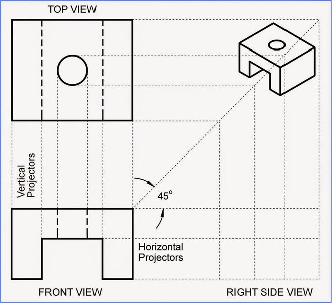
An illustration showing the principle of orthographic projection with lines of sight (projectors) creating a 2D view from a 3D object.
When a line is inclined to both the Horizontal Plane (HP) and Vertical Plane (VP), its projections (front view and top view) will not show its true length. Instead, they will be foreshortened. The true length of a line is only visible when the line is parallel to the plane of projection, and the line of sight is perpendicular to that plane. To find the true length and true inclinations of a line inclined to both planes, specific construction methods like the rotation method or auxiliary view method are employed.
The Problem: Line CD Analysis
Let's consider the given problem: End "C" of line CD is 13 mm above HP and 51 mm in front of VP. End "D" is 12 mm behind the VP and 35 mm below the HP. The end projectors are 52 mm apart. We need to draw the projections, find the True Length (TL), true inclinations with HP (\(\theta\)) and VP (\(\phi\)), Horizontal Trace (HT), and Vertical Trace (VT).
Initial Setup: Drawing the Reference Line (XY) and Projectors
The first step in any orthographic projection problem is to draw the reference line, typically denoted as XY. This line represents the intersection of the HP and VP. Points above XY are in the HP (top view), and points below XY are in the VP (front view), assuming a first-angle projection, or vice-versa for third-angle projection. Since end D is behind VP and below HP, we are likely working in a scenario that might involve multiple quadrants, or it's a specific instruction for how the views are laid out. For typical engineering drawing conventions, first-angle projection places the top view below the front view, and third-angle projection places the top view above the front view. Given the description of point D (behind VP and below HP), it implies the third quadrant. However, the standard practice for learning is usually first-angle. Let's assume a standard first-angle projection for consistency in methodology, and adapt if the points fall into other quadrants as implied by the problem.
- Draw an XY line.
- Draw two projectors 52 mm apart. These projectors will be vertical lines on which the front and top views of points C and D will lie.
Locating the Projections of End C (C', c) and End D (D', d)
Based on the problem statement:
- Point C:
- 13 mm above HP: This is the distance for the front view (C'). So, C' will be 13 mm above the XY line.
- 51 mm in front of VP: This is the distance for the top view (c). So, c will be 51 mm below the XY line (for first angle projection).
- Point D:
- 35 mm below HP: This is the distance for the front view (D'). So, D' will be 35 mm below the XY line.
- 12 mm behind VP: This is the distance for the top view (d). For standard first-angle projection, points behind VP are not typically drawn below the XY line in the top view in the usual sense. However, if we interpret "behind VP" as moving into a different quadrant (e.g., 2nd or 3rd), the top view 'd' would be above the XY line. Given "below HP" also, this places D in the third quadrant. In the third quadrant, the front view is below XY, and the top view is above XY. So, D' is 35 mm below XY, and 'd' is 12 mm above XY.
Connect C' to D' to get the front view (FV) of the line CD. Connect c to d to get the top view (TV) of the line CD.
Determining True Length and Inclinations
Since the line CD is inclined to both HP and VP (as indicated by different positions of its ends relative to both planes), its front and top views will be foreshortened. To find the true length and true inclinations, we can use the rotation method.
The Rotation Method Explained
The rotation method involves making one of the projections (either front or top view) parallel to the XY line by rotating it. When a view is parallel to the XY line, its projection on the other plane will show the true length. This technique allows us to "unfold" the line to see its actual length and angles.
Finding True Length (TL) and Inclination with HP (\(\theta\))
- Make Top View Parallel to XY:
- From point c (top view of C), draw an arc with radius equal to the length of the top view (cd) until it intersects a horizontal line drawn from c. Let this new point be d1.
- Now, the line c-d1 is parallel to the XY line.
- Project to Front View:
- From d1, draw a vertical projector upwards.
- From D' (front view of D), draw a horizontal locus line.
- The intersection of the vertical projector from d1 and the horizontal locus line from D' gives D1'.
- Connect for True Length:
- Connect C' to D1'. The length C'D1' is the True Length (TL) of the line.
- The angle that C'D1' makes with the horizontal line drawn from C' is the true inclination with the HP (\(\theta\)).
Finding True Length (TL) and Inclination with VP (\(\phi\))
- Make Front View Parallel to XY:
- From point C' (front view of C), draw an arc with radius equal to the length of the front view (C'D') until it intersects a horizontal line drawn from C'. Let this new point be D2'.
- Now, the line C'D2' is parallel to the XY line.
- Project to Top View:
- From D2', draw a vertical projector downwards.
- From d (top view of D), draw a horizontal locus line.
- The intersection of the vertical projector from D2' and the horizontal locus line from d gives d2.
- Connect for True Length:
- Connect c to d2. The length c-d2 is also the True Length (TL) of the line (it should be the same as C'D1').
- The angle that c-d2 makes with the horizontal line drawn from c is the true inclination with the VP (\(\phi\)).
The concepts of true length and inclination are critical for ensuring that manufactured components align with design specifications. The foreshortening effect can be visually represented using a radar chart, illustrating how perceived lengths change based on projection angles.
Visualizing Projections and True Length Attributes
The radar chart below provides a conceptual visualization of how different attributes of the line CD might be perceived or calculated. It emphasizes the contrast between apparent lengths and true lengths, and the significance of traces. The values are illustrative, reflecting how different aspects contribute to a comprehensive understanding of the line in 3D space.
Locating the Traces of the Line (HT & VT)
Traces are points where a line intersects the principal planes of projection. The Horizontal Trace (HT) is the point where the line meets the Horizontal Plane, and the Vertical Trace (VT) is where it meets the Vertical Plane. Locating these traces helps further define the line's position in space.
Finding the Horizontal Trace (HT)
The HT is found where the front view of the line intersects the XY line. The corresponding point on the top view, projected from this intersection, will be the HT.
- Extend the front view (C'D') until it intersects the XY line. Mark this point as H'. (This H' is the projection of HT on VP).
- From H', draw a vertical projector downwards.
- Extend the top view (cd) until it intersects the vertical projector from H'. Mark this intersection as HT. (This HT is the actual horizontal trace of the line).
Finding the Vertical Trace (VT)
The VT is found where the top view of the line intersects the XY line. The corresponding point on the front view, projected from this intersection, will be the VT.
- Extend the top view (cd) until it intersects the XY line. Mark this point as V. (This V is the projection of VT on HP).
- From V, draw a vertical projector upwards.
- Extend the front view (C'D') until it intersects the vertical projector from V. Mark this intersection as VT. (This VT is the actual vertical trace of the line).
It is crucial to be methodical in extending lines and drawing projectors to ensure accuracy in locating the traces. These points offer valuable information about where the line enters and exits the various quadrants of the projection system.
Summary of Line Projection Parameters
Below is a table summarizing the key parameters and their significance in the projection of a line, particularly when it's inclined to both principal planes.
| Parameter | Description | Relevance |
|---|---|---|
| True Length (TL) | The actual, unforeshortened length of the line in 3D space. | Critical for accurate design, manufacturing, and construction; obtained by rotation or auxiliary view methods. |
| Angle with HP (\(\theta\)) | The true angle the line makes with the Horizontal Plane. | Determines the line's inclination relative to the ground or base plane. |
| Angle with VP (\(\phi\)) | The true angle the line makes with the Vertical Plane. | Determines the line's inclination relative to a vertical wall or front plane. |
| Front View (C'D') | The projection of the line onto the Vertical Plane. | Shows the height and (foreshortened) length, essential for elevation details. |
| Top View (cd) | The projection of the line onto the Horizontal Plane. | Shows the depth and (foreshortened) length, essential for plan details. |
| Horizontal Trace (HT) | The point where the line intersects the Horizontal Plane. | Indicates where the line "pierces" the ground plane. |
| Vertical Trace (VT) | The point where the line intersects the Vertical Plane. | Indicates where the line "pierces" the front/back wall plane. |
| End Projectors Distance | The perpendicular distance between the vertical lines connecting corresponding end points of the line in the front and top views. | Defines the overall horizontal spread of the line's projection. |
Deep Dive into Line Projection Methods
The complexity of projecting a line inclined to both HP and VP necessitates specialized techniques. The core idea is to transform the line's position relative to the projection planes until its true length is revealed. This is achieved by either rotating the line or by introducing an auxiliary projection plane. The problem presented here relies on the rotation method, which is a common and effective approach in engineering graphics.
The Significance of Traces in Multi-Quadrant Projections
When a line passes through multiple quadrants, its traces become particularly insightful. For instance, if one end is in the first quadrant (above HP, in front of VP) and the other is in the third quadrant (below HP, behind VP), the line must cross both the HP and VP at some point. The HT would typically be on the HP (below XY in the top view, on XY in the front view) and the VT on the VP (above XY in the front view, on XY in the top view) if the line goes from 1st to 3rd. However, in our specific problem, with C in 1st quadrant and D in 3rd quadrant, the HT will be on the top view extension (above XY) and the VT on the front view extension (below XY). This helps confirm the quadrant transitions.
Illustrative Video Resource
To further solidify your understanding of how to find the true length of a line, especially when it's inclined to both the Horizontal Plane (HP) and Vertical Plane (VP), watching a step-by-step demonstration can be invaluable. The video below illustrates the process using a common method, providing a visual guide that complements the theoretical explanations. This particular video is highly relevant as it focuses on the projection of straight lines, which directly applies to the problem at hand by detailing the procedures for lines inclined to both planes and how to derive their true lengths and inclinations.
A tutorial video demonstrating the projection of a line inclined to both HP and VP, and methods to find its true length.
Frequently Asked Questions
Conclusion
Drawing the projections of a line inclined to both principal planes and subsequently determining its true length, true inclinations, and traces, is a cornerstone skill in engineering graphics. It demands a meticulous understanding of orthographic projection principles and the application of specific construction techniques like the rotation method. By systematically following the steps outlined, even complex spatial relationships can be accurately represented on a two-dimensional drawing. This fundamental knowledge is critical for engineers and designers to effectively communicate intricate geometric information, ensuring precision in all stages from conceptualization to manufacturing.
Recommended Further Exploration
- How to draw projections of solids in engineering graphics?
- Understanding auxiliary views in orthographic projection.
- Practical applications of true length in engineering design.
- Differences between first angle and third angle projection.
Referenced Search Results
 hg4u.files.wordpress.com
 martingraphicseee.blogspot.com