
Unlocking Life-Saving Technology: A Deep Dive into Medical Ventilator Design
Discover the essential components and intricate connections that power modern medical ventilators, crucial for critical care.
Key Insights into Ventilator Production
- Comprehensive Component Overview: Modern medical ventilators integrate diverse systems, including precise gas delivery, sophisticated control mechanisms, and crucial safety features.
- Interconnected Systems: The ventilator functions as a closed-loop system where power, gas supply, sensors, and control units work in harmony to regulate airflow and pressure, guided by real-time feedback.
- Critical Safety and Monitoring: Built-in alarms, pressure relief valves, and continuous monitoring systems are paramount to ensure patient safety and effective operation.
Producing a medical ventilator for critical care applications is a highly complex undertaking that demands meticulous attention to detail, adherence to stringent medical standards, and comprehensive engineering expertise. These life-saving devices are designed to assist or completely take over a patient's breathing, delivering oxygen and removing carbon dioxide, making them indispensable in ICUs, emergency settings, and even some home care scenarios. From sophisticated, computer-controlled units to simpler, automated designs, each ventilator relies on a precise integration of various components to ensure safe and effective respiratory support.
The following guide details the essential components required for a typical medical ventilator and outlines their interconnections. This information is derived from comprehensive and reliable sources, providing a foundational understanding for anyone looking to delve into ventilator production.
The Core Components of a Medical Ventilator
A modern medical ventilator is composed of several critical subsystems, each playing a vital role in its overall function. These systems work in concert to deliver precise respiratory support.
Power and Control Systems: The Brain and Heart of the Ventilator
The operational integrity of a ventilator begins with its power source and sophisticated control mechanisms. These are the fundamental elements that enable the device to function autonomously and respond to patient needs.
Reliable Power Source
Ventilators require a stable and continuous power supply. Typically, they operate from mains electricity, but critical care applications necessitate robust backup battery systems. These batteries ensure uninterrupted operation during power outages or patient transport, which is vital for maintaining life support. A dedicated power management system handles battery charging, power distribution, and failover mechanisms to switch seamlessly between power sources.
Microcontroller or Embedded Processor
At the core of the ventilator's intelligence is a microprocessor or programmable logic controller (PLC). This computerized system acts as the "brain," automating and controlling all gas delivery characteristics, timing, and settings. It processes data from various sensors and sends commands to actuators and valves, ensuring precise ventilation parameters such as tidal volume, respiratory rate, and pressure limits are maintained. The software running on this processor dictates the ventilation modes (e.g., volume control, pressure control), alarm triggers, and overall operational logic.
User Interface Controls
The user interface (UI) provides medical professionals with the means to interact with and regulate the ventilator. This typically includes buttons, touchscreens, and rotary knobs that allow for the precise setting of ventilation parameters like fractional inspired oxygen concentration (FiO2), positive end-expiratory pressure (PEEP), respiratory rate, and tidal volume. An intuitive UI is crucial for quick and accurate adjustments in critical situations.
Valves and Actuators
These components are the mechanical effectors of the control system. Electromechanical solenoid valves or pneumatic valves are used to open, close, and regulate gas pathways with extreme precision. Proportional valves are particularly important for fine-tuning gas flow and pressure. Actuators are responsible for mechanical movements, such as compressing a breathing bag in automated designs or driving pistons to control gas delivery.
Gas Delivery System: Orchestrating Airflow
The gas delivery system ensures that the patient receives the correct mixture of gases at the appropriate pressure, temperature, and humidity.
Gas Sources and Blending
Ventilators connect to external gas sources, typically compressed medical air and oxygen tanks or wall outlets. A crucial component is the Gas Blender or Gas Mixer, which precisely combines these gases to achieve the desired oxygen concentration (FiO2), usually between 21% and 100%. Modern blenders often use electronically-controlled proportional valves for accuracy.
Gas Accumulator/Reservoir
After blending, the gas is often directed to a Gas Accumulator or reservoir. This component stores a volume of the mixed gas, helping to smooth out flow fluctuations and ensure a consistent supply before it is delivered to the patient.
Inspiratory and Expiratory Flow Regulation
The Inspiratory Flow Regulator, often employing solenoid valves, controls the rate and volume of gas delivered into the patient's lungs during inhalation. Conversely, the Expiratory Pressure Regulator, commonly known as a PEEP Valve (Positive End-Expiratory Pressure valve), maintains a positive pressure in the airways at the end of exhalation. This prevents the collapse of the alveoli and improves oxygenation. One-way valves are also essential to ensure unidirectional gas flow, preventing rebreathing of exhaled air and maintaining the integrity of the inspiratory and expiratory paths.
Humidification Equipment
To prevent drying of the patient's respiratory tract and to ensure comfortable and safe ventilation, humidification equipment is integrated into the system. This adds warmth and moisture to the inspired gas, typically conditioning it to body temperature and humidity levels. Components can include heated humidifier chambers or heat moisture exchangers (HMEs).
Patient Circuit and Filters
The Patient Circuit consists of tubing that connects the ventilator to the patient's airway, usually via an endotracheal tube. This circuit includes inspiratory and expiratory limbs. Crucially, Bacterial/Viral Filters are strategically placed in the circuit to prevent the spread of pathogens between the patient and the ventilator, protecting both the patient and medical staff.
Monitoring and Safety Features: Safeguarding the Patient
Continuous monitoring and robust safety mechanisms are non-negotiable in ventilator design to ensure patient well-being and alert clinicians to potential issues.
Sensors
A suite of sensors continuously monitors vital parameters:
- Pressure Sensors: Measure various pressures within the circuit, such as peak inspiratory pressure (PIP), mean airway pressure, and plateau pressure.
- Airflow Sensors: Ensure the desired volume and rate of gas are delivered and exhaled.
- Oxygen Analyzers: Verify the oxygen concentration (FiO2) of the delivered gas.
- End-tidal CO2 (EtCO2) Sensors: Measure carbon dioxide levels in exhaled breath, providing insight into ventilation effectiveness.
Alarms and Safety Mechanisms
Alarms are critical safety features that alert medical staff to deviations from normal operating parameters or critical events. These can include warnings for high or low pressure, disconnection, power failure, apnea (cessation of breathing), or incorrect oxygen concentration. Pressure Release Valves act as fail-safes, automatically venting excess pressure to prevent barotrauma to the patient's lungs. Battery backup and fail-safe mechanisms ensure operation or a safe shutdown in case of critical system failures.
Conceptualizing Ventilator Connections: A Schematic Overview
Understanding how these components are connected is essential for designing a functional ventilator. While a detailed engineering blueprint requires specialized CAD software, a simplified block diagram illustrates the core functional flow and interdependencies.
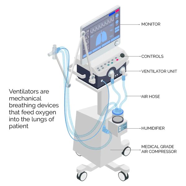
Anatomy of a medical ventilator illustrating various components and their approximate locations.
The Flow of Air and Information
The ventilator operates as a sophisticated closed-loop system, where gases are prepared, delivered, monitored, and regulated in a continuous cycle.
Gas Preparation and Inspiration Pathway
Compressed medical air and oxygen from their sources enter the Gas Blending Unit. Here, the precise FiO2 is achieved. The blended gas then flows into a Gas Reservoir to ensure stable pressure. From the reservoir, the gas passes through the Inspiratory Flow Control Valve, which regulates the volume and rate of delivery. Next, it enters the Humidifier to be warmed and moistened. Finally, this conditioned gas travels through the Inspiratory Circuit Tubing, passing through a Bacterial/Viral Filter, before reaching the patient via an Endotracheal Tube.
Exhalation Pathway and Gas Scavenging
After inhalation, the patient exhales. The exhaled gases flow back through the Expiratory Circuit Tubing. This limb includes another Bacterial/Viral Filter and the Expiratory Valve, which incorporates the PEEP Valve to maintain positive pressure. Exhaled gases are then safely vented to the atmosphere or, in some closed-system designs, routed through a CO2 filter for recycling.

A simplified schematic showing the interaction of various ventilator components, from gas input to patient interface.
The Interconnected Control Loop
The true intelligence of the ventilator lies in its control and feedback loop. The Control Unit (Microcontroller/Processor) is the central processing unit. It receives continuous data from various Sensors (pressure, flow, O2, CO2) placed throughout the inspiratory and expiratory limbs of the circuit. Based on this real-time feedback and the programmed ventilation settings, the control unit sends commands to the Valves and Actuators, dynamically adjusting gas flow, pressure, and volume. The Power Management System supplies electricity to all electronic components, including the control unit, sensors, and actuators. The Alarm System & Display are also connected to the control unit, providing visual and auditory alerts and displaying real-time waveforms of pressure, flow, and volume for monitoring by clinicians.
Here is a simplified mindmap illustrating the main functional blocks and their relationships within a medical ventilator system:
(O2, Medical Air)"] B2["Gas Blending Unit"] B3["Gas Accumulator"] B4["Inspiratory Flow Regulator"] B5["Humidification Equipment"] B6["Expiratory Valve (PEEP)"] B7["Patient Circuit
(Tubing, Connectors)"] B8["Filters
(Viral/Bacterial)"] C["Control & Processing"] C1["Microcontroller/Processor"] C2["User Interface"] C3["Valves & Actuators"] D["Monitoring & Safety"] D1["Sensors
(Pressure, Flow, O2, CO2)"] D2["Alarms & Indicators"] D3["Pressure Release Valves"] D4["Battery Backup & Fail-Safes"]
This mindmap visually represents the hierarchical and interconnected nature of the ventilator's functional blocks, highlighting how each major component contributes to the overall system.
Performance Considerations and Design Trade-offs
When producing a medical ventilator, it's essential to consider various performance aspects and potential design trade-offs. The device must be robust, reliable, and capable of operating under diverse conditions. The following radar chart provides a comparative view of essential performance attributes, offering a perspective on the balance required in design.
This radar chart illustrates a hypothetical comparison between a high-end ICU-grade ventilator and a simpler, emergency/DIY ventilator. ICU-grade ventilators prioritize precision of gas delivery, reliability, and advanced safety features, often at a higher cost and with more complex maintenance. Emergency/DIY ventilators, in contrast, may prioritize ease of use, cost-effectiveness, and maintainability, potentially sacrificing some precision or advanced features for rapid deployment.
Understanding Patient Circuits: An Essential Visual Guide
A crucial aspect of ventilator operation involves the patient circuit, which is the direct interface with the patient. This video by George provides an excellent overview of the components within the patient circuit and how they are assembled.
The video "Mechanical Ventilation: Patient Circuits: Part 1: Components" offers a visual breakdown of the tubes, filters, humidifiers, and connectors that make up the patient circuit. It is highly relevant because it demonstrates the physical components that directly interact with the patient's airway, illustrating the practical assembly and the importance of elements like humidifiers for patient comfort and safety. This visual context is invaluable for anyone seeking to understand the hands-on aspects of ventilator assembly and operation.
Comprehensive Component Summary Table
To summarize, the following table lists the essential components by category, along with their primary function and typical examples, providing a quick reference for ventilator production.
| Component Category | Primary Function | Typical Examples |
|---|---|---|
| Power Source | Provides stable electrical power and ensures continuous operation. | AC power supply, backup batteries, power management system. |
| Gas Sources | Supply compressed medical gases for breathing. | Oxygen (O2) tanks, medical air wall outlets. |
| Gas Blending & Storage | Mixes gases to desired concentration and stores it. | Gas blender/mixer (proportional valves), gas accumulator/reservoir. |
| Flow & Pressure Regulation | Controls timing, volume, and pressure of gas delivery and exhalation. | Inspiratory flow regulator, expiratory valve (PEEP valve), one-way valves. |
| Gas Conditioning | Adds warmth and moisture to inspired gas. | Humidification equipment (heated humidifier, HMEs). |
| Patient Interface | Connects ventilator to patient's airway for gas delivery and return. | Inspiratory/expiratory tubing/circuits, endotracheal tube, T-connectors. |
| Filtration | Prevents contamination and protects patient/staff from pathogens. | Viral/bacterial filters. |
| Control System | Regulates all ventilator functions based on set parameters and feedback. | Microcontroller/embedded processor, user interface (touchscreens, buttons). |
| Sensors | Monitors vital parameters for real-time feedback and adjustment. | Pressure sensors, airflow sensors, oxygen analyzers, EtCO2 sensors. |
| Actuators | Drives mechanical movements to control gas flow and pressure. | Solenoid valves, proportional valves, pneumatic actuators. |
| Safety Features | Protects patient and alerts staff to issues. | Alarms (audio/visual), pressure relief valves, fail-safe mechanisms. |
| Structural Components | Houses and connects internal components, ensures physical integrity. | Enclosure, mounting hardware, medical-grade tubing connectors. |
Frequently Asked Questions (FAQ)
Conclusion
The production of a medical ventilator is a testament to sophisticated engineering, integrating pneumatic, electronic, and control systems to provide essential respiratory support. Every component, from the power supply to the patient circuit, plays a critical role in ensuring the safe, precise, and reliable operation of this life-saving device. Adherence to rigorous medical standards and continuous monitoring are paramount. This detailed overview of components and their connections provides a solid foundation for understanding the complexities involved in ventilator design and production.
Recommended Further Exploration
- Explore detailed CAD schematics for medical ventilator design.
- Discover open-source ventilator projects and their full component lists.
- Understand the regulatory standards and certifications required for medical ventilators.
- Investigate the engineering principles behind mechanical ventilation.