
Understanding Multiview Drawings: Identifying False Statements
A comprehensive analysis to identify the incorrect statement about multiview drawings.
Key Highlights
- Multiview drawings use parallel lines to project an object's views.
- Dashed lines represent hidden features in multiviews.
- A key characteristic is that only one principal face is visible in each view.
Multiview drawings are a fundamental technique in engineering and design, used to represent 3D objects in 2D. This method relies on orthographic projection to create several views of an object, each showing it from a different direction. These views collectively provide a complete geometric description of the object. Let's evaluate each of the provided statements to identify the one that is not true.
Analyzing the Statements About Multiview Drawings
The question asks us to identify which statement about multiview drawings is incorrect. To do this, we will analyze each statement in the context of orthographic projection and multiview drawing principles.
Statement A: Parallel Projection Lines
The first statement suggests that lines projecting from the object to the picture plane are parallel to each other. This is a fundamental characteristic of orthographic projection. In orthographic projection, all projection lines are parallel to each other and perpendicular to the projection plane. This ensures that the resulting 2D view accurately represents the dimensions of the object without any perspective distortion. Therefore, statement A is true.
Statement B: Dashed Lines for Hidden Features
Statement B asserts that dashed lines are used to show portions of an object that are hidden from sight in any view. This is a standard convention in technical drawings. Dashed lines, also known as hidden lines, indicate edges or features that are behind visible surfaces. This allows engineers and designers to understand the complete geometry of the object, even those parts that are not directly visible in a particular view. Therefore, statement B is true.
Statement C: Multiple Principal Faces in One View
Statement C proposes that the object is positioned with respect to the picture plane so that more than one principal face is visible in any one view. This statement is false. In multiview drawings, the object is oriented so that only one principal face is visible in each primary view (front, top, side). The purpose of multiview projection is to show each face of the object in its true size and shape, which is only possible when the face is parallel to the picture plane. If multiple faces were visible in one view, it would distort the true representation of each face. Therefore, statement C is not true.
Statement D: Projection of a Face onto a Picture Plane
Statement D states that each view is produced by projecting a face of the object onto a picture plane. This accurately describes the process of creating a multiview drawing. Each view represents a projection of one face of the object onto a plane that is parallel to that face. This is how the true size and shape of each face are captured in the drawing. Therefore, statement D is true.
Statement E: True Size and Shape Representation
Statement E suggests that points projected onto the picture plane show the true size and shape of the face of the object. This is a key characteristic of orthographic projection. When a face of the object is parallel to the picture plane, its projection accurately represents its true dimensions and shape. This is why orthographic projections are used in engineering drawings, where precise measurements are critical. Therefore, statement E is true.
The Importance of Orthographic Projection in Multiview Drawings
Orthographic projection is the backbone of multiview drawings, offering a precise method for representing 3D objects in 2D. This technique is essential in engineering and design for creating accurate and detailed technical drawings. The key is that all projection lines are parallel to each other and perpendicular to the projection plane, ensuring that the resulting views maintain the true dimensions of the object.
The utilization of orthographic projection allows for the creation of multiview drawings, which typically consist of a front view, top view, and a side view. Each view provides specific information about the object from a different perspective. By combining these views, a comprehensive understanding of the object's geometry is achieved. This is crucial for manufacturing, construction, and other fields where precise communication of design information is necessary.
One of the main advantages of orthographic projection is that it eliminates perspective distortion. Unlike perspective projections, where objects appear smaller as they recede into the distance, orthographic projections maintain consistent scaling across the entire view. This makes it easier to take accurate measurements directly from the drawing.
Furthermore, orthographic projections are used to create auxiliary views, which are projections onto planes that are not parallel to the principal faces of the object. These views are necessary when the object has inclined or oblique surfaces that are not fully represented in the standard views. By projecting these surfaces onto auxiliary planes, their true size and shape can be revealed.
Visualizing Hidden Details with Dashed Lines
In multiview drawings, it's often necessary to represent features that are not directly visible from a particular viewpoint. This is where dashed lines, also known as hidden lines, come into play. These lines are used to indicate edges, surfaces, and features that are located behind visible surfaces.
The use of dashed lines is a critical convention in technical drawing. Without them, it would be impossible to fully understand the geometry of an object. Hidden lines allow engineers and designers to visualize the internal structure and hidden features of a part, ensuring that all necessary information is communicated clearly.
For example, consider a rectangular block with a hole drilled through it. In the front view, the hole would be represented by two dashed lines indicating the edges of the hole that are not visible from the front. Similarly, in the top view, dashed lines might be used to show the bottom surface of a recessed feature.
The proper use of dashed lines requires careful consideration of the object's geometry and the viewpoint of each projection. It's important to ensure that the dashed lines are accurately placed and clearly distinguishable from visible lines. This helps to avoid confusion and misinterpretation of the drawing.
Hidden lines are not only used to represent internal features but also to indicate the boundaries of surfaces that are obscured by other parts of the object. This is particularly important in complex assemblies where multiple components overlap each other.
Multiview Drawing Views
Multiview drawings typically consist of three standard views: the front view, the top view, and one side view (either the left side view or the right side view). Each view provides a different perspective of the object, allowing for a complete geometric description.
Front View
The front view is generally considered the primary view of the object. It is typically chosen to show the object in its most natural or functional orientation. The front view usually displays the most important features and details of the object.
Top View
The top view is a projection of the object as seen from above. It is aligned directly above the front view, sharing the same width dimension. The top view provides information about the depth of the object, which may not be apparent in the front view.
Side View
The side view, either left or right, shows the object from the side. It is typically aligned horizontally with the front view, sharing the same height dimension. The side view provides additional information about the depth and shape of the object, particularly features that may not be visible in the front or top views.
Together, these three views provide a comprehensive representation of the object's geometry. They allow engineers and designers to visualize the object in three dimensions and understand its overall shape and features. In some cases, additional views may be necessary to fully describe the object, such as auxiliary views for inclined surfaces or section views to reveal internal details.
Orthographic vs. Perspective Projection
To fully appreciate the principles of orthographic projection, it's helpful to compare it with perspective projection, another common method of representing 3D objects in 2D. While both techniques serve the same general purpose, they differ significantly in their approach and the resulting visual representation.
In perspective projection, parallel lines converge as they recede into the distance, creating the illusion of depth and realism. This is similar to how the human eye perceives the world, with objects appearing smaller as they move further away. Perspective projections are often used in architectural renderings, illustrations, and computer graphics to create visually appealing images.
In contrast, orthographic projection maintains parallel lines, meaning that objects do not appear to diminish in size with distance. This results in a more technical and precise representation, where measurements can be taken directly from the drawing without any perspective distortion. Orthographic projections are preferred in engineering and manufacturing because they provide accurate geometric information.
The choice between orthographic and perspective projection depends on the specific application. If the goal is to create a realistic and visually appealing image, perspective projection is often the better choice. However, if the goal is to communicate precise geometric information, orthographic projection is the preferred method.
Practical Applications of Multiview Drawings
Multiview drawings are used extensively in various fields, including:
-
Engineering: Creating detailed plans for machines, structures, and systems.
-
Manufacturing: Providing precise instructions for producing parts and assembling products.
-
Architecture: Developing construction documents that show the layout and dimensions of buildings.
-
Design: Communicating design ideas and specifications to clients and stakeholders.
By using multiview drawings, professionals can ensure that their designs are accurately communicated and properly executed. This helps to prevent errors, reduce costs, and improve the overall quality of the final product.
Illustrative Table of Drawing Types
The following table summarizes the key differences between orthographic and perspective projections, highlighting their respective strengths and weaknesses.
| Feature | Orthographic Projection | Perspective Projection |
|---|---|---|
| Parallel Lines | Remain Parallel | Converge |
| Size with Distance | Constant | Decreases |
| Perspective Distortion | None | Present |
| Accuracy | High | Lower |
| Applications | Engineering, Manufacturing | Architecture, Illustration |
Mastering Multiview Drawings
To solidify your understanding of multiview drawings, check out this video explaining how to create orthographic views from isometric projections:
The video "Beginner's Guide to Orthographic Projection: Multi-View Drawing" is highly relevant because it provides a step-by-step tutorial on creating orthographic views, specifically the front, top, and right side views, from an isometric view. This is a fundamental skill in engineering drawing, as it allows designers and engineers to accurately represent 3D objects in 2D. The video's beginner-friendly approach makes it accessible to those new to the concept, and the clear explanations and visual demonstrations help to reinforce the key principles of orthographic projection. By watching this video, viewers can gain a practical understanding of how to create multiview drawings and improve their technical drawing skills.
Image Gallery: Visual Examples of Multiview Drawings
This section showcases examples of multiview drawings, illustrating how different views combine to represent a 3D object in 2D.
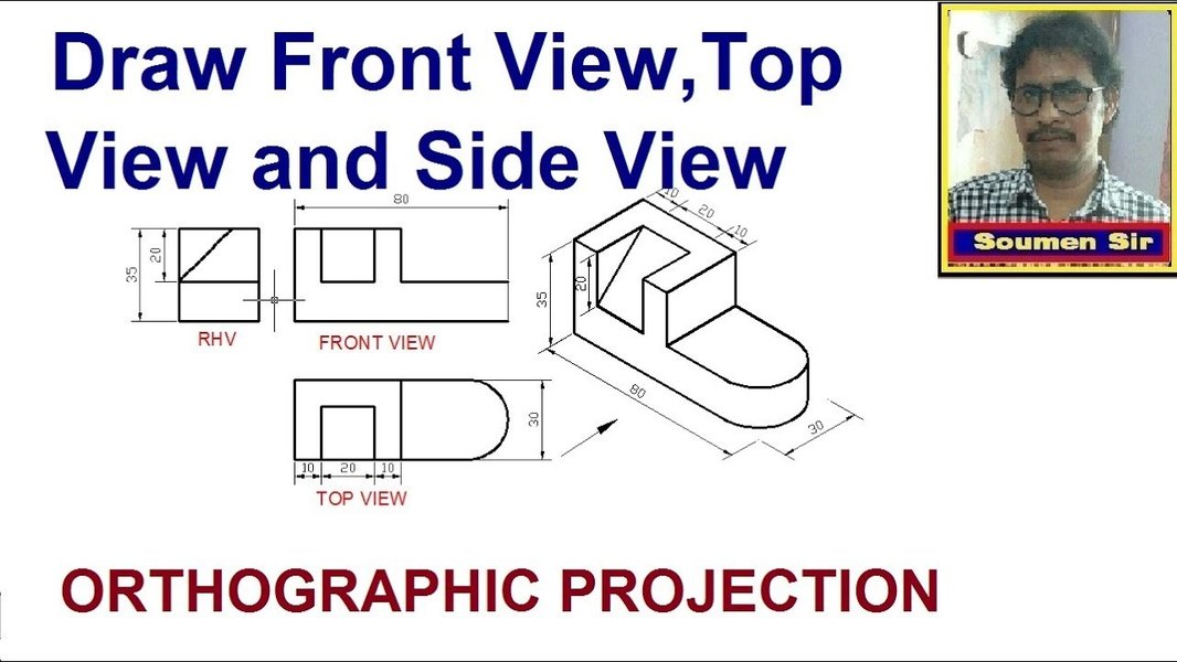
Example of Orthographic Projection
In the image, note how each view (front, top, and side) provides specific details about the object, and how hidden lines are used to represent features that are not directly visible. By studying these examples, you can gain a better understanding of how multiview drawings are constructed and interpreted.

Orthographic Views
These views are essential for accurately communicating the design and manufacturing requirements of an object. Each view is carefully constructed to ensure that all necessary dimensions and features are clearly represented.
FAQ
What is the main purpose of multiview drawings?
The main purpose of multiview drawings is to represent a 3D object in 2D by providing multiple views that show the object from different directions. This allows for a complete and accurate geometric description of the object.
Why are dashed lines used in multiview drawings?
Dashed lines, also known as hidden lines, are used to indicate edges, surfaces, and features that are hidden from sight in a particular view. This helps to convey the complete geometry of the object, including its internal structure.
What are the standard views in a multiview drawing?
The standard views in a multiview drawing are the front view, the top view, and one side view (either the left side view or the right side view). These views provide a comprehensive representation of the object from different perspectives.
How does orthographic projection differ from perspective projection?
Orthographic projection maintains parallel lines and constant scaling, while perspective projection converges parallel lines and reduces the size of objects with distance. Orthographic projection is used for accurate geometric representation, while perspective projection is used for creating realistic visual images.
In what fields are multiview drawings commonly used?
Multiview drawings are commonly used in engineering, manufacturing, architecture, and design to communicate precise geometric information and ensure accurate execution of designs.
Conclusion
In summary, the statement that is not true for multiview drawings is: "the object is positioned with respect to the picture plane so that more than one principal face is visible in any one view." Multiview drawings are designed to show only one principal face in each view to accurately represent the object's dimensions and features.
References
 static.sdcpublications.com
Last updated April 11, 2025