
Understanding the Significance of Process Flow Diagrams (PFDs)
A Comprehensive Analysis of PFD Applications in Industrial Plant Engineering
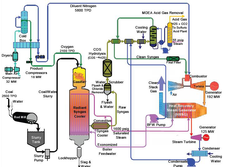
Key Highlights
- Visual Process Overviews: PFDs offer clear, simplified representations of complex process systems.
- Enhanced Communication: These diagrams serve as a universal language bridging interdisciplinary teams.
- Safety and Optimization: By mapping process flows, PFDs are instrumental in identifying bottlenecks and managing risks.
Introduction to Process Flow Diagrams (PFDs)
Process Flow Diagrams (PFDs) are vital graphical tools extensively utilized within industrial plant engineering. They encapsulate the framework of process systems by visually outlining the flow of materials, energy, and information throughout a facility. The importance and applications of PFDs extend across various industrial sectors such as chemical, petrochemical, power generation, and manufacturing.
The Roles and Purpose of PFDs
Visualizing Complex Processes
One of the key roles of PFDs is to render complex industrial processes into an understandable visual format. In large-scale production or processing plants, systems often consist of numerous interconnected units. A PFD outlines these units along with the pathway of materials and energy flows between them, which simplifies detailed systems into legible, high-level diagrams. This visual representation helps engineers and operators to grasp intricate interconnections and reliably plan operational adjustments.
Facilitating Effective Communication
In multidisciplinary projects, stakeholders such as process engineers, mechanical engineers, safety inspectors, and management all depend on accurate representations to lead discussions and make informed decisions. PFDs serve as a common language, ensuring that everyone is aligned in their understanding of the process dynamics. This uniformity improves collaboration, reduces misinterpretation, and lays the groundwork for more detailed schematics like Piping and Instrumentation Diagrams (P&IDs).
Supporting Planning and Design
During the initial phases of industrial plant design, PFDs are indispensable tools for outlining the system architecture. They help define the project scope, identify critical components, and pinpoint potential risks. Engineers use PFDs to plan equipment placement, assess material usage, and estimate the distribution of utilities such as steam, water, or air. Furthermore, PFDs support regulatory compliance and safety analyses by ensuring that all critical process stages are scrutinized before implementation.
Enhancing Process Analysis and Optimization
Process Flow Diagrams are utilized not only for conceptual designs but also for continuous process improvement. By visually mapping the pathways and interactions, engineers can identify inefficiencies, potential bottlenecks, and redundant processes. This analytical capability allows for the identification of process optimization opportunities, thereby reducing production costs and improving efficiency. For example, by recognizing areas of energy wastage or material recycling inefficiencies, adjustments can be made to streamline the operation. This analytical approach also contributes to improved control strategies that are implemented over time.
Risk, Safety, and Regulatory Compliance
Safety is paramount in industrial environments, and PFDs have a crucial role in the risk management process. By providing a comprehensive view of the process, PFDs assist in identifying hazardous variables and operational risks. Detailed diagrams help in developing mitigation strategies and emergency response plans by highlighting where failures or accidents might occur. Additionally, these diagrams form an essential part of documentation required for regulatory compliance and audits, ensuring that the facility adheres to safety and environmental standards.
Detailed Applications of PFDs in Industrial Plant Engineering
Process Design and Engineering
In the early design stages of industrial plants, the PFD is often one of the first diagrams produced. It provides a blueprint that outlines the main equipment, phases, and interactions that define the process. Engineers use PFDs to:
- Define process boundaries and main control loops.
- Determine the placement of major components such as reactors, separators, and heat exchangers.
- Outline the sequence of unit operations and guarantee that they are logically connected.
Example: Conceptual Plant Layout
A typical PFD may display the flow of raw materials entering a chemical processing plant, the sequence of necessary reactions, separation units, and the final exit streams, all while indicating where energy inputs such as steam or cooling water are applied.
Operational Efficiency and Troubleshooting
During plant operations, PFDs are revised to reflect changes and improvements. They serve as a reference document in troubleshooting situations where the process might be underperforming. Fault analysis and maintenance planning are performed based on the clear demarcation of process stages in the PFDs. By quickly isolating where inefficiencies or performance deviations occur within the diagram, corrective measures can be promptly executed.
Optimizing Process Flow
An operational review might reveal that a specific unit operation, such as a distillation column, is causing delays. A close examination of its representation in the PFD would help determine if the bottleneck is due to equipment limitations or poor design integration, leading to targeted interventions that improve throughput.
Training and Onboarding
PFDs are also an important component in employee training and onboarding. New hires can refer to these diagrams to quickly understand the overview of the plant processes, the dependencies between units, and the sequence of operations. This educational use of PFDs ensures that even individuals who are not specialists in process engineering can grasp the general workflow and operational challenges of the plant.
Documentation for Ongoing Reference
In many cases, PFDs are included in standard operating procedures (SOPs) and technical documentation. This dual role as both educational material and serving as a basis for operational decisions makes them indispensable for maintaining operational continuity and safety standards.
Utility and Resource Management
Another essential application of PFDs is in the planning and management of utilities that support plant operations. They provide clarity on how energy, water, and other utilities are integrated into the process.
Utility Integration
By including streams that represent utility flows, PFDs assist in mapping out utility allocation and ensuring that these resources are efficiently deployed. For instance, a PFD might depict how steam is distributed from a central boiler to various parts of the plant, thereby helping engineers plan for capacity and redundancy.
Comparative Analysis: PFDs vs. Detailed Schematics
While Process Flow Diagrams provide a broad overview, they are usually the precursor to more detailed diagrams such as Piping and Instrumentation Diagrams (P&IDs). Understanding the distinction between these tools enhances their effective use:
| Aspect | PFD | P&ID |
|---|---|---|
| Scope | High-level overview of the process | Detailed view including piping, instrumentation, and control loops |
| Detail | Emphasis on major equipment and process flow | In-depth details of valves, sensors, and interconnections |
| Usage | Early design phase, process visualization, and troubleshooting | Detailed engineering, installation, and maintenance procedures |
| Audience | Engineers, management, and safety teams | Technical staff, maintenance crews, and process controllers |
Practical Benefits of Utilizing PFDs
Streamlined Communication Across Departments
By encapsulating the process in a concise format, PFDs provide a visual common ground for diverse teams. This common understanding minimizes the likelihood of misinterpretation and accelerates problem-solving discussions. Whether it is a meeting with engineers, operators, or maintenance technicians, the PFD acts as an effective guide that reinforces overall process understanding.
Facilitating Risk and Safety Management
In scenarios where process hazards are a concern, PFDs prove vital. They not only highlight the flow but also pinpoint areas where safety measures need enhancement. For example, by clearly marking the points where high-pressure systems or hazardous chemicals are introduced into the process, engineers are better equipped to design appropriate safeguarding measures. This visibility ensures that potential accident risks are systematically assessed and mitigated.
Aiding in Process Troubleshooting and Maintenance
In operational settings, unexpected disturbances or system shutdowns require rapid diagnosis. The high-level schematic provided by a PFD is invaluable in these circumstances. Maintenance teams can quickly correlate malfunctioning parts of the process with their places in the diagram, thereby reducing downtime and enabling swift corrective actions. This structured approach is essential for both routine maintenance and emergency response.
Improving Operational Efficiency Through Continuous Feedback
By reviewing PFDs periodically, organizations can monitor the performance of critical process parameters and adjust operations continuously for improved efficiency. The reuse of these diagrams as feedback instruments helps reinforce the culture of continuous improvement. Adjustments in process control parameters and operational practices—based on the insights garnered from PFD reviews—directly contribute to reduced waste and optimized resource usage.
The Lifecycle of a PFD in Industrial Plant Engineering
Conceptual Design and Feasibility Studies
Initially, during the conceptual design stage, engineers use PFDs to outline the general process layout. At this phase, ideas are brainstormed and feasibility studies are performed. The PFD here serves as a preliminary map that captures the essential process steps and establishes a foundation for future detailed planning. It provides a strategic view that forms the basis of cost estimations, environmental impact assessments, and regulatory reviews.
Detailed Process Engineering and Integration
Once a conceptual design is approved, the focus shifts to detailed process engineering. In this phase, the PFD is utilized to integrate various subsystem designs, ensuring that the overall process flow is coherent. It acts as a reference framework, facilitating the transition from preliminary designs to fully developed systems like P&IDs. Engineers can validate that all subsidiary systems, such as utility distributions and control loops, are aligned with the high-level process.
Operational Review and Process Optimization
Throughout the operational life of the plant, continuous evaluation of process performance is essential for maintaining efficiency and safety. Over time, process engineers revisit the PFD to analyze performance data, discuss modifications, and update the diagram to reflect changes due to process improvements or unexpected operational challenges. This lifecycle approach ensures that PFDs remain current documents that accurately guide plant operations.
Integration of PFDs in Digital Plant Management
With advancements in technology, the integration of digital tools has further enhanced the utility of Process Flow Diagrams. Modern engineering environments utilize software platforms that support dynamic PFDs, integrating them with real-time data and simulation models. Such integration not only enables remote monitoring of plant processes but also permits virtual troubleshooting, energy efficiency analysis, and predictive maintenance strategies. The digital evolution in PFD usage represents a significant leap forward in the adoption of technology-driven process management.
Digital Simulation and Process Optimization
Digital models derived from PFDs allow engineers to simulate process conditions and potential modifications before implementing changes physically. These simulations can mathematically model various scenarios using advanced algorithms. For example, engineers might use simulation to explore how changes in material flow impact system pressures and energy consumption, thereby allowing them to refine the process design to achieve optimal performance.
Real-Time Data Integration
Linking PFDs with live data streams facilitates a real-time feedback loop where operational adjustments can be made on-the-fly. This capability is particularly valuable for addressing transient states or emergency conditions within the plant. The ability to visualize real-time process behavior, overlaid on traditional PFDs, creates a dynamic environment that enhances both management capabilities and operational safety.
References
- The Importance of Procedure Flow Charts in Streamlining Operations - Business Process Experts
- Process Flow Diagram (PFD) - What is Piping
- Understanding the Benefits of a Process Flow Diagram - Trainual
-
Process Flow Diagram - ScienceDirect Topics
- Process Flow Diagram - Wikipedia
Recommended Queries
Last updated March 7, 2025