
Unveiling Piston Dynamics: Velocity Calculation in High-Performance Engines
A Deep Dive into Reciprocating Engine Kinematics and Performance
Understanding the intricate motion of a piston within a reciprocating internal combustion engine is fundamental to comprehending engine performance, efficiency, and durability. The continuous up-and-down (reciprocating) movement of the piston, driven by the combustion of fuel and air, is ingeniously converted into the rotational motion of the crankshaft. This transformation is achieved through a connecting rod, forming a crucial kinematic linkage within the engine. Analyzing the piston's velocity at various points in its cycle is essential for optimizing engine design, predicting wear, and ensuring reliable operation, especially in high-speed applications.
Key Insights into Piston Velocity and Engine Mechanics
- Piston velocity is constantly changing: The piston momentarily stops at Top Dead Center (TDC) and Bottom Dead Center (BDC), accelerating to its maximum speed somewhere in between. This non-uniform motion is a key characteristic of reciprocating engines.
- Geometric parameters are critical: Factors such as crank radius, connecting rod length, and engine speed (RPM) directly dictate the piston's position, velocity, and acceleration at any given crank angle.
- High piston velocity impacts durability: While higher piston velocity can lead to increased power output, it also elevates friction, wear, and 'g' loading on engine components, necessitating robust material selection and precise engineering.
The Heart of the Engine: Reciprocating Motion Explained
A reciprocating engine, often referred to as a piston engine, harnesses the energy released from the combustion of a fuel-air mixture to generate mechanical work. This process typically involves a series of strokes within a cylinder where a piston moves back and forth. The most common type is the four-stroke engine, which completes a cycle in four distinct phases: intake, compression, combustion (power stroke), and exhaust. The linear motion of the piston is then translated into rotational motion via a connecting rod and crankshaft assembly. This continuous conversion of linear to rotational energy is the driving force behind many vehicles and power generation systems.
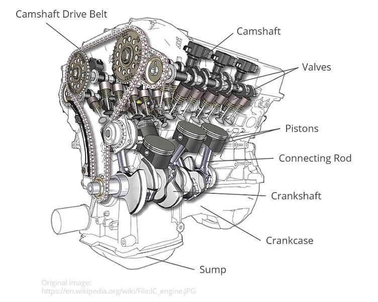
A detailed cutaway view illustrating the key components of a reciprocating engine, including the piston, connecting rod, and crankshaft.
Understanding the Piston's Journey
The piston's motion is far from simple harmonic motion. Its velocity and acceleration are influenced by the angular position of the crankshaft and the geometric relationship between the crank and connecting rod. At Top Dead Center (TDC) and Bottom Dead Center (BDC), the piston's velocity momentarily becomes zero as it changes direction. The maximum piston velocity, however, occurs when the connecting rod and crank throw are nearly perpendicular, typically close to 70-80 degrees from TDC, depending on the rod-to-stroke ratio.
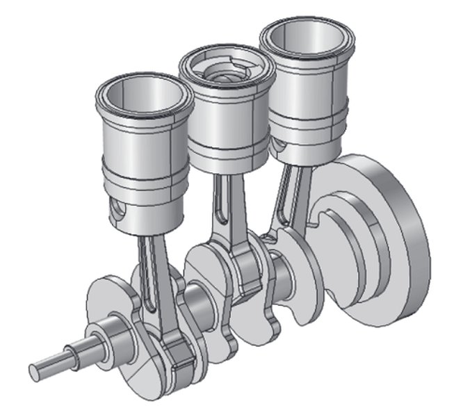
The Role of the Connecting Rod and Crankshaft
The connecting rod serves as the crucial link, converting the piston's linear motion into the crankshaft's rotational motion. The length of the connecting rod relative to the crank radius (often expressed as the rod-to-stroke ratio) significantly impacts the piston's kinematic characteristics. A shorter connecting rod (lower ratio) leads to higher peak piston velocities and accelerations, while a longer rod (higher ratio) results in smoother piston motion but less available torque at lower RPMs.
Calculating Piston Velocity: A Detailed Analysis
To accurately determine the instantaneous velocity of a piston, we must consider the kinematic relationships within the crank-slider mechanism. The provided problem asks for the velocity of a piston in the y-axis direction (perpendicular to the crankshaft axis) at a specific crank angle. This requires a more detailed kinematic analysis than the mean piston speed formula.
Formulas for Piston Kinematics
The instantaneous velocity of the piston ( \(V_p\) ) can be derived using calculus, considering the crank angle ( \(\theta\) ), crank radius ( \(r\) ), connecting rod length ( \(l\) ), and crankshaft angular velocity ( \(\omega\) ).
The angular velocity \(\omega\) (in radians per second) is first calculated from the given engine speed in revolutions per minute (RPM):
\[ \omega = \frac{2 \pi \times \text{RPM}}{60} \]The general equation for the piston's instantaneous velocity is given by:
\[ V_p = r \omega \left( \sin\theta + \frac{r}{2l} \sin(2\theta) \right) \]Where:
- \(V_p\) is the instantaneous piston velocity.
- \(r\) is the crank radius.
- \(\omega\) is the angular velocity of the crankshaft.
- \(\theta\) is the crank angle from TDC.
- \(l\) is the connecting rod length.
Applying the Values to the Problem
Given the following parameters:
- Engine speed = 6600 rev/min
- Crank radius ( \(r\) ) = 41 mm = 0.041 m
- Connecting rod length ( \(l\) ) = 144 mm = 0.144 m
- Crank angle ( \(\theta\) ) = 190° from TDC
Step-by-Step Calculation
- Convert RPM to Angular Velocity (\(\omega\)): \[ \omega = \frac{2 \pi \times 6600}{60} \text{ rad/s} \] \[ \omega \approx 691.15 \text{ rad/s} \]
- Convert Crank Angle to Radians: \[ \theta = 190^\circ \times \frac{\pi}{180^\circ} \text{ rad} \] \[ \theta \approx 3.316 \text{ rad} \]
- Calculate the ratio \(r/l\): \[ \frac{r}{l} = \frac{0.041}{0.144} \approx 0.2847 \]
- Substitute values into the piston velocity formula: \[ V_p = (0.041 \text{ m}) \times (691.15 \text{ rad/s}) \times \left( \sin(190^\circ) + \frac{0.041}{2 \times 0.144} \sin(2 \times 190^\circ) \right) \] \[ V_p = 28.337 \times \left( \sin(190^\circ) + \frac{0.041}{0.288} \sin(380^\circ) \right) \] \[ V_p = 28.337 \times \left( -0.1736 + 0.14236 \times 0.1736 \right) \] \[ V_p = 28.337 \times \left( -0.1736 + 0.0247 \right) \] \[ V_p = 28.337 \times (-0.1489) \] \[ V_p \approx -4.2205 \text{ m/s} \]
The velocity of the piston in the y-axis direction when the crankshaft has rotated 190° from TDC is approximately -4.22 m/s. The negative sign indicates that the piston is moving downwards (towards BDC) at this instant.
Kinematic diagram illustrating the angles and lengths involved in piston motion.
Understanding the Significance of Piston Velocity
Piston velocity is not merely a theoretical calculation; it has profound implications for engine design, performance, and longevity. The dynamic forces generated by the reciprocating mass of the piston, connecting rod, and associated components increase quadratically with velocity. This leads to significant inertial stresses at high RPMs, which engineers must account for through material selection and component design.
Impact on Engine Performance and Durability
High piston velocities promote efficient cylinder filling and exhaust scavenging when coupled with appropriate intake/exhaust tract designs and valve timing. However, exceeding design limits can lead to increased friction, greater heat generation, and accelerated wear on critical engine components like piston rings, cylinder walls, and bearings. The "g-loading" on reciprocating parts, a direct consequence of piston acceleration, also dictates the required strength of these components for high-velocity operation.
Mean vs. Instantaneous Piston Speed
While the instantaneous piston velocity varies throughout the cycle, the mean piston speed is often used as a key indicator of engine potential and component durability. The mean piston speed is a simpler calculation: \(\text{Mean Piston Speed (fpm)} = (\text{Stroke} \times 2 \times \text{RPM}) / 12\). However, for detailed dynamic analysis and component stress calculations, the instantaneous velocity and acceleration are essential, as demonstrated in our calculation.
Illustrating Piston Motion Characteristics
To further illustrate the multifaceted considerations in engine design, a radar chart can visually represent the various performance and durability attributes influenced by piston kinematics. This chart provides a qualitative comparison of how different aspects are prioritized or affected by the choices in engine geometry and operating conditions.
Radar Chart illustrating key engine design considerations influenced by piston dynamics.
This chart highlights the trade-offs inherent in engine design. High-RPM engines, like the one in our calculation, excel in power output potential and volumetric efficiency but often face challenges in peak velocity management, durability, and friction. Conversely, long-stroke engines might offer better durability and vibration control at the expense of peak power potential.
Visualizing Piston Engine Operation
To further contextualize the piston velocity calculation, it's beneficial to see how the various components of an internal combustion engine work together. The following video provides a clear animation of a V8 engine, illustrating the movement of pistons, connecting rods, and the crankshaft as they collaborate to generate power.
An animated explanation of a V8 engine's operation, demonstrating the synchronized motion of its components.
This animation vividly demonstrates the four-stroke cycle: intake, compression, combustion, and exhaust, and how the linear motion of the pistons is converted into the rotational energy of the crankshaft. Understanding this cyclical process is key to appreciating the dynamic forces and velocities at play within the engine.
Comparative Analysis of Engine Kinematics
Different engine designs and operating conditions yield varied kinematic characteristics. Below is a table summarizing how various parameters affect piston motion and overall engine dynamics, building upon the principles discussed in our calculation.
| Parameter | Influence on Piston Velocity | Impact on Engine Performance | Impact on Engine Durability |
|---|---|---|---|
| Engine RPM | Directly proportional to mean and instantaneous velocity. | Higher RPM generally means higher power output. | Increases inertial forces, friction, and wear. |
| Crank Radius (Stroke) | Longer stroke increases piston travel distance per revolution, leading to higher velocities. | Longer stroke can increase torque at lower RPMs. | Higher peak velocities and accelerations, leading to increased stress on components. |
| Connecting Rod Length | Longer rod reduces angularity, smoothing piston motion and reducing peak velocity/acceleration for a given stroke. | Can reduce side loading on cylinder walls, improving efficiency. | Improves durability by reducing stress and friction. |
| Rod-to-Stroke Ratio | Higher ratio (longer rod relative to stroke) reduces maximum piston velocity and acceleration. | Affects engine's "feel" and torque characteristics. | Significantly impacts component longevity; higher ratios are generally preferred for durability. |
| Piston Mass | Heavier piston increases inertial forces at high velocities. | Higher inertia can hinder rapid acceleration and deceleration. | Increases stress on the connecting rod, crankshaft, and bearings. |
Frequently Asked Questions (FAQ)
Conclusion
Calculating the instantaneous velocity of a piston, as demonstrated for an engine operating at 6600 rev/min with specific crank and connecting rod dimensions, reveals a precise snapshot of its motion. The result of approximately -4.22 m/s indicates a rapid downward movement of the piston at the specified 190° crank angle. This calculation, rooted in fundamental kinematic principles, underscores the dynamic forces and engineering complexities inherent in reciprocating internal combustion engines. A deep understanding of piston kinematics is indispensable for optimizing engine performance, enhancing fuel efficiency, and ensuring the long-term durability of these remarkable machines that power much of our modern world. The interplay between engine speed, component dimensions, and dynamic forces forms the bedrock of robust engine design, constantly pushing the boundaries of what is possible in power generation and motion.
Recommended Searches
- How to calculate piston acceleration at any crank angle?
- What is the impact of rod-to-stroke ratio on engine design and performance?
- What are the major forces acting on reciprocating engine components?
- How do the kinematics differ between 2-stroke and 4-stroke internal combustion engines?