
Optimizing Compressed Air Purging and Utility Drain Time for a 25m2 Coil Jacket Reactor
A comprehensive guide to efficient reactor operation, focusing on compressed air purging and utility drain times in coil jacket reactors.
Key Considerations for Reactor Operation
- Efficient Purging: Removing air and moisture is crucial to prevent unwanted reactions and maintain product quality.
- Optimized Drain Time: Minimizing drain time enhances throughput and reduces downtime.
- Safety and Maintenance: Proper purging and draining procedures contribute to a safer operating environment and extend equipment life.
Understanding Reactor Jacket Purging and Draining
In chemical and pharmaceutical processes, jacketed reactors are essential for controlling the temperature of the reactor contents. A jacket surrounds the main reactor vessel, allowing a heat transfer fluid (such as steam, hot oil, or cooling water) to circulate and either heat or cool the reactor. Efficient operation of these reactors depends on effective purging and draining procedures, especially in coil jacket reactors. Coil jacket reactors use a coiled pipe wrapped around the reactor vessel to circulate the heat transfer fluid.
The Importance of Purging
Purging involves removing unwanted substances, such as air, moisture, or residual chemicals, from the reactor jacket. Air and moisture can interfere with heat transfer efficiency and potentially cause corrosion or unwanted reactions. Purging with compressed air ensures that the system is free of contaminants before and after operation.
Why is Purging Necessary?
- Prevents Corrosion: Moisture can lead to corrosion of the reactor and jacket materials.
- Enhances Heat Transfer: Air pockets in the jacket reduce the efficiency of heat transfer.
- Maintains Product Quality: Contaminants can react with the reactants, leading to undesired by-products.
- Safety: Removing volatile or reactive substances prevents hazardous situations.
Optimizing Purging Time
Determining the standard compressed air purging time for a 25m2 coil jacket reactor involves several factors. The size of the jacket, the complexity of the coil design, and the pressure of the compressed air all play a role. Unfortunately, there is no universally "standard" time because each system's requirements vary.
Factors Influencing Purging Time:
- Jacket Volume: Larger jackets require more time to purge.
- Coil Complexity: More complex coil designs may trap air, requiring longer purging times.
- Air Pressure: Higher air pressure can speed up the purging process but must be within the equipment's safety limits.
- Moisture Level: Higher moisture levels require longer purging to ensure complete removal.
A practical approach involves monitoring the outlet air during purging. The purging process should continue until the exiting air is free of moisture and contaminants. This can be assessed using moisture indicators or by measuring the dew point of the outlet air.
The Importance of Utility Draining
Draining involves removing the heat transfer fluid from the reactor jacket after operation. Complete and timely draining is essential for preventing corrosion, preparing for maintenance, and switching between heating and cooling cycles.
Why is Draining Necessary?
- Prevents Corrosion: Residual heat transfer fluid can cause corrosion over time.
- Facilitates Maintenance: Draining allows for inspection and repair of the jacket and coils.
- Enables Temperature Changes: Complete draining is necessary when switching from heating to cooling or vice versa.
Optimizing Drain Time
The utility drain time for a 25m2 coil jacket reactor also depends on several factors. These include the type of heat transfer fluid, the design of the jacket, and the efficiency of the draining system. Like purging time, there is no universal standard, but optimization is crucial.
Factors Influencing Drain Time:
- Fluid Viscosity: More viscous fluids drain more slowly.
- Jacket Design: Complex coil designs may trap fluid, requiring longer drain times.
- Drainage System: Efficient drainage systems, including properly sized drain valves and slopes, can reduce drain time.
- Fluid Temperature: Temperature affects viscosity; warmer fluids generally drain faster.
To optimize drain time, ensure that the reactor jacket is designed with adequate drainage points and slopes. Using a pump to assist draining can also significantly reduce the time required. Regular maintenance of drain valves and lines is essential to prevent blockages and ensure efficient draining.
Practical Considerations and Best Practices
While specific times for purging and draining vary, some general guidelines and best practices can help optimize these processes for a 25m2 coil jacket reactor.
Best Practices for Purging:
- Use Dry Compressed Air: Ensure the compressed air is dry to prevent introducing moisture into the system.
- Monitor Outlet Air: Use moisture indicators or dew point measurements to determine when purging is complete.
- Purge at Moderate Pressure: Use a pressure that is high enough to effectively remove contaminants but low enough to avoid damaging the equipment.
- Ensure Proper Ventilation: Purge in a well-ventilated area to avoid the accumulation of hazardous vapors.
Best Practices for Draining:
- Ensure Complete Drainage: Visually inspect the jacket to ensure all fluid has been removed.
- Use a Pump if Necessary: A pump can help remove residual fluid from the jacket.
- Regular Maintenance: Inspect and maintain drain valves and lines to prevent blockages.
- Consider Fluid Compatibility: Ensure that the draining process is compatible with the heat transfer fluid and any disposal requirements.
Enhancing Understanding with Visual Aids
Visual aids can significantly improve the understanding of jacketed reactor systems, including the coil jacket design and the purging/draining process.
This video from Radleys demonstrates how to dry and purge a reactor vessel prior to use. It highlights the importance of removing moisture to prevent unwanted chemical reactions. In jacketed reactors, purging ensures that no contaminants affect the chemistry inside the vessel. This is particularly critical in sensitive chemical processes where even trace amounts of moisture can alter reaction outcomes or damage the final product. By following proper drying and purging procedures, operators can maintain optimal reaction conditions, enhance product yield, and reduce the risk of equipment corrosion or failure.
Visualizing Coil Jacket Reactors
Coil jacket reactors come in various designs, each tailored to specific process requirements. The following images illustrate different configurations and components of these reactors.
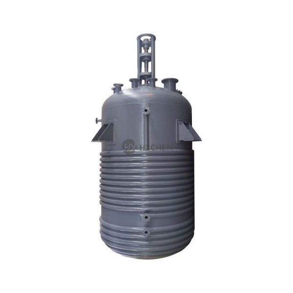
Limpet Coil Reactor
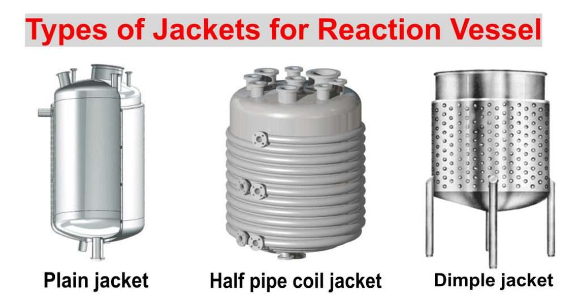
Types of Jackets for Reaction Vessels
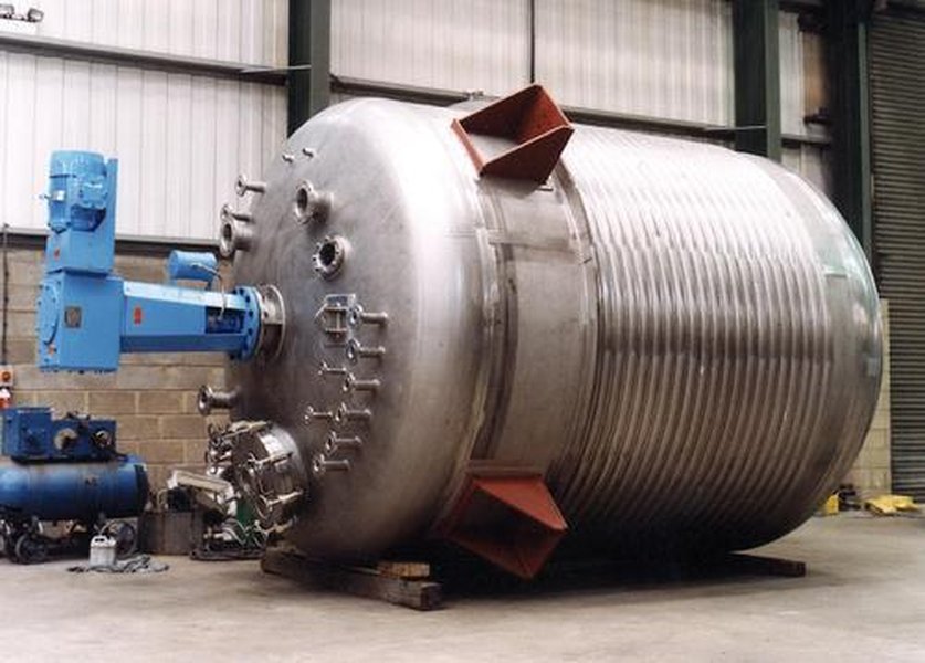
Limpet Coil Reactor
These images showcase the external coil design, which allows for efficient heat transfer. The coils are typically welded to the outer surface of the reactor vessel, creating a jacket through which heat transfer fluids can circulate. This design is particularly effective for processes requiring precise temperature control, as the fluid can evenly distribute heat (or remove it) across the reactor surface. Different coil configurations, such as spiral or helical patterns, can be chosen based on the specific thermal requirements of the reaction. Furthermore, the construction materials (usually stainless steel or other corrosion-resistant alloys) ensure that the reactor can withstand the harsh chemical environments commonly encountered in industrial applications. Proper installation and maintenance of these coil systems are critical for ensuring optimal performance and longevity of the reactor.
Illustrative Table of Purging and Draining Considerations
Here's a table summarizing the key considerations for optimizing purging and draining times in a 25m2 coil jacket reactor. This table consolidates the factors influencing these processes and provides actionable insights for efficient reactor operation. By addressing these considerations, operators can ensure optimal performance, minimize downtime, and maintain a safe working environment.
| Process | Factors Influencing Time | Optimization Strategies |
|---|---|---|
| Purging |
|
|
| Draining |
|
|
FAQs About Reactor Jacket Purging and Draining
Q1: How often should I purge the reactor jacket?
The frequency of purging depends on the specific application and operating conditions. Generally, purge before starting a new batch or after any maintenance that may introduce air or moisture into the jacket. Regular monitoring of the jacket's condition can help determine the optimal purging schedule.
Q2: What type of compressed air is best for purging?
Dry, oil-free compressed air is best for purging to prevent introducing moisture or contaminants into the reactor jacket. Using a compressed air dryer and filter can ensure the air meets these requirements.
Q3: How can I tell if the reactor jacket is completely drained?
Visually inspect the jacket through any inspection ports. If complete visual inspection is not possible, measure the amount of fluid drained and compare it to the known volume of the jacket. Any significant discrepancy indicates that the jacket is not completely drained.
Q4: Can I use nitrogen instead of compressed air for purging?
Yes, nitrogen can be used as an alternative to compressed air. Nitrogen is an inert gas, which can be beneficial in preventing oxidation or other unwanted reactions. However, ensure that the nitrogen is also dry and oil-free.
Q5: What safety precautions should I take when purging and draining the reactor jacket?
Always wear appropriate personal protective equipment (PPE), such as gloves and eye protection. Ensure that the area is well-ventilated to prevent the accumulation of hazardous vapors. Follow all safety procedures outlined in the equipment manuals and safety data sheets (SDS) for the heat transfer fluid.
References
Last updated April 11, 2025