
Creating a Reverse Induction Generator Prototype Tapping into Schumann Resonance
Exploring the Intersection of Induction Generation and Natural Frequencies
This guide outlines the creation of a simple prototype for a reverse induction electric generator that aims to interact with or piggyback on the Schumann resonance frequencies or their harmonics. The focus is on utilizing commonly available materials while incorporating special-order parts where essential for function.
Key Insights
- Induction Generators: An induction motor can function as a generator when driven above its synchronous speed, utilizing the principle of reverse induction.
- Schumann Resonance: These are a set of spectrum peaks in the Earth's electromagnetic field, with the primary frequency around 7.83 Hz and several harmonics.
- Prototype Concept: The prototype aims to explore if a small-scale induction generator can be influenced or augmented by the extremely low frequencies of the Schumann resonance through resonant interaction or other coupling mechanisms.
Understanding the Core Concepts
What is a Reverse Induction Generator?
An electric motor and an electric generator are fundamentally similar in their operation; a motor converts electrical energy into mechanical energy, while a generator does the reverse, converting mechanical energy into electrical energy. Specifically, an induction motor can act as an induction generator. This occurs when the rotor of the induction motor is driven at a speed greater than its synchronous speed while connected to an electrical power system or appropriately configured with capacitors for self-excitation in a standalone system.
The principle behind this "reverse induction" is that when the rotor spins faster than the magnetic field rotating around the stator (synchronous speed), the relative motion induces a voltage and current in the rotor opposite to what happens in motor mode. This induced rotor current then creates its own magnetic field that interacts with the stator's magnetic field, causing power to flow back into the electrical system or load.
Common applications of induction generators include wind turbines, microhydro systems, and some regenerative braking systems where a prime mover (wind, water, or mechanical force) drives the motor shaft above synchronous speed, effectively turning the motor into a generator. They are often preferred for grid-tied applications due to their self-synchronizing nature when connected to the grid.
Here's a simple visual illustrating the concept:
Figure 1: An electric motor being used in reverse as a generator.
What are Schumann Resonances?
Schumann resonances are global electromagnetic resonances in the cavity between the Earth's surface and the ionosphere. They are primarily excited by lightning discharges. The fundamental frequency of the Schumann resonance is approximately 7.83 Hz, with several distinct harmonic peaks occurring at around 14.07 Hz, 20.25 Hz, 26.41 Hz, 32.45 Hz, and so on. These frequencies are in the extremely low frequency (ELF) portion of the electromagnetic spectrum.
While the direct effects of Schumann resonance on electrical power systems or small-scale generators are not typically considered significant in conventional electrical engineering, the query proposes exploring a potential interaction or "piggybacking" on these natural frequencies. This part of the project delves into a more experimental or theoretical realm, exploring potential resonant effects or subtle energy interactions at these very low frequencies.

Figure 2: A commercially available Schumann Resonance Generator, typically used for therapeutic purposes.
The Concept of Piggybacking
The idea of "piggybacking" on the Schumann resonance for power generation is highly speculative from a standard electrical engineering perspective. The energy levels associated with Schumann resonances are extremely low. However, for the purpose of a prototype exploring this concept, we can interpret "piggybacking" as attempting to use the Schumann frequencies or their harmonics as a trigger, a resonant enhancer, or a subtle energy source to potentially influence or augment the output of a small induction generator. This would likely involve attempting to create a system that resonates at or near one of the Schumann frequencies and see if this resonance can in any way affect the induction generation process.
Prototype Design and Components
Choosing an Induction Motor/Generator
For a simple prototype, a small, readily available induction motor can be used. Single-phase induction motors are common in household appliances (like exhaust fans, as seen in one of the video sources) and are suitable for a small-scale experiment. The size of the motor will depend on the desired scale of the prototype, but something in the range of a few watts to a few tens of watts would be manageable and cost-effective.
Sourcing the Motor
Common sources for small induction motors include:
- Discarded appliances (fans, pumps, washing machines)
- Hobby electronics suppliers
- Online marketplaces (eBay, Amazon)
Ensure the motor is in good working condition.
Mechanism to Drive the Generator
To make the induction motor act as a generator, its rotor needs to be driven above its synchronous speed. The synchronous speed of an AC induction motor is determined by the frequency of the power supply and the number of poles in the motor (\(N_s = \frac{120 \times f}{P}\), where \(N_s\) is synchronous speed in RPM, \(f\) is frequency in Hz, and \(P\) is the number of poles). For a 60 Hz supply and a common 4-pole motor, the synchronous speed is 1800 RPM. You will need to drive the rotor faster than this.
Driving Mechanism Options
- Another Motor: A DC motor or a variable-speed AC motor can be used to drive the induction motor shaft via a coupling or belt system. This allows for controlled speed adjustment to exceed the synchronous speed.
- Manual Crank: For a very simple, low-cost prototype, a hand crank system can be devised, though maintaining a consistent speed above synchronous speed might be challenging.
- External Mechanical Source: If available, a small engine or other mechanical power source could be adapted.
For a prototype focused on electrical interaction, using another motor as the prime mover offers better control over the rotational speed.
Circuitry for Induction Generator Operation
An induction motor operating as a generator requires reactive power for excitation. If connected to the grid, this is supplied by the grid itself. For standalone operation, capacitors are typically connected across the stator terminals to provide the necessary reactive power and allow for self-excitation. The capacitance value is critical and depends on the motor's characteristics and the desired operating conditions.
Capacitor Bank for Self-Excitation
Determining the correct capacitance requires some experimentation or calculations based on the motor's parameters. Start with a calculated value based on online resources for self-excited induction generators and adjust as needed. You will need non-polarized capacitors suitable for AC operation (motor run capacitors are ideal).
The generator's voltage and frequency will be influenced by the speed and the capacitance value.
Incorporating Schumann Resonance Interaction
This is the most experimental part of the prototype. Directly generating usable power from the minuscule energy of Schumann resonances is not feasible with simple means. The approach here is to create a system component that might be sensitive to or resonate at Schumann frequencies and see if this has any observable effect on the induction generator's output or behavior.
Potential Methods for Schumann Interaction
- Resonant Coil: Construct a large coil of wire tuned to resonate at or near 7.83 Hz (or a harmonic). This would require a significant number of turns and potentially a large form factor due to the low frequency. The coil could be placed in proximity to the induction generator.
- ELF Signal Generator and Antenna: Use a low-frequency signal generator (special order part) to produce a signal at a Schumann frequency and feed it to a coil or antenna placed near the generator. This allows for controlled testing of specific frequencies.
- Piezoelectric or Electrostrictive Coupling: Explore if materials exhibiting piezoelectric or electrostrictive properties at very low frequencies could be incorporated to convert subtle environmental ELF vibrations into small electrical signals that might influence the generator's control circuitry (if any) or magnetic field. This is highly theoretical for this application.
Given the constraints of a simple prototype, the resonant coil or ELF signal generator methods are more approachable.
Measurement and Observation
To assess the prototype's performance and observe any potential influence from the Schumann resonance interaction component, you will need measurement tools.
Essential Measurement Equipment
- Multimeter: To measure voltage, current, and resistance.
- Oscilloscope: Crucial for observing waveforms and identifying frequency components and distortions.
- Frequency Counter or Spectrum Analyzer (Optional but Recommended): To accurately measure frequencies present in the output and analyze harmonic content.
- AC Power Meter: To measure the output power of the generator.
Building the Prototype: Step-by-Step (Conceptual)
Step 1: Prepare the Induction Motor
Obtain a small induction motor. If it's a motor from an appliance, you may need to disassemble it to access the motor unit. Identify the stator windings and rotor.
Step 2: Set up the Driving Mechanism
Mount the induction motor securely. Couple the shaft of the induction motor to the shaft of the driving motor (or the manual crank). Ensure proper alignment to minimize vibration.
Step 3: Connect the Capacitor Bank
Connect the appropriately sized capacitor bank across the stator terminals of the induction motor. Ensure all connections are secure and insulated.
Step 4: Incorporate the Schumann Interaction Component
Based on your chosen method (resonant coil or ELF generator), build or obtain the component. Place the resonant coil in close proximity to the induction generator's stator. If using an ELF generator, connect the output to a coil or antenna placed near the generator.
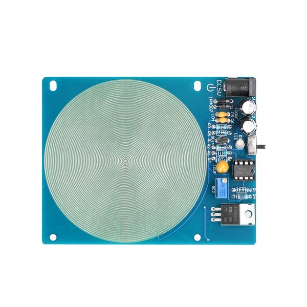
Figure 3: An ultra-low frequency pulse generator module often used in DIY Schumann resonance devices.
Step 5: Set up Measurement Equipment
Connect your multimeter, oscilloscope, and other measurement tools to the output terminals of the induction generator. Be cautious when working with electrical circuits.
Step 6: Testing and Observation
Start the driving mechanism and bring the induction motor's speed above its synchronous speed. Observe if the generator begins to produce voltage. Adjust the speed of the prime mover and potentially the capacitance value to optimize generation.
Once stable generation is achieved, activate or position the Schumann interaction component. Carefully observe the output waveform on the oscilloscope, looking for any changes in voltage, frequency stability, or the presence of frequency components related to the Schumann resonance or its harmonics. Use the spectrum analyzer, if available, for more detailed frequency analysis.
Experiment with different Schumann frequencies (if using an ELF generator) and observe any corresponding changes in the generator's output.
Considerations and Challenges
Building this prototype involves several considerations and potential challenges:
- Low Energy Levels of Schumann Resonance: The energy associated with Schumann resonances is very low, making it difficult to directly harness for power generation. Any observed effects are likely to be subtle and challenging to measure accurately.
- Resonant Frequency Tuning: Precisely tuning a coil or circuit to resonate at extremely low frequencies like 7.83 Hz can be challenging and may require specialized components or significant physical size.
- Noise and Interference: The measurement of subtle effects at low frequencies can be obscured by electrical noise and interference from other sources. Careful shielding and grounding may be necessary.
- Motor Parameters: The specific characteristics of the induction motor used will significantly impact its performance as a generator and the required capacitance for self-excitation.
- Safety: Working with electrical circuits and rotating machinery requires caution. Ensure all connections are safe and properly insulated.
Expected Outcomes (Experimental)
Based on conventional physics, it is unlikely that a significant amount of electrical power can be generated or augmented by simply "piggybacking" on the Schumann resonances with a small-scale prototype. However, the experiment could potentially reveal:
-
Subtle influences on the stability or waveform of the generated voltage when the Schumann interaction component is active.
-
Resonant effects in the generator's output circuitry at or near Schumann frequencies, even if not leading to significant power generation.
-
Insights into the challenges of interacting with extremely low-frequency electromagnetic fields.
HTML Table: Prototype Components
Here is a table summarizing the key components for the prototype:
| Component | Description | Availability (Common vs. Special Order) |
|---|---|---|
| Induction Motor | Small single-phase or three-phase induction motor (e.g., from a fan) | Common |
| Driving Mechanism | DC motor, variable-speed AC motor, or manual crank | Common (Motors), Common/Custom (Mounting/Coupling) |
| Capacitor Bank | Non-polarized AC capacitors for self-excitation | Common (Electronic Suppliers) |
| Resonant Coil or ELF Generator | Large wire coil tuned to Schumann frequency OR Ultra-low frequency signal generator module | Common (Wire), Special Order (Signal Generator Module) |
| Mounting Hardware | Materials to secure motors and components (wood, metal brackets, screws) | Common |
| Wiring and Connectors | Electrical wire, terminals, and connectors | Common |
| Measurement Equipment | Multimeter, Oscilloscope, Frequency Counter/Spectrum Analyzer (optional) | Common (Multimeter, Oscilloscope), Special Order (Spectrum Analyzer) |
Relevant Video Resources
Here is a video demonstrating the principle of turning an electric motor into a generator:
Video 1: Demonstrating an electric motor functioning as a generator. This illustrates the basic principle of converting mechanical energy to electrical energy using a motor in reverse.
Frequently Asked Questions (FAQ)
Can a regular electric motor be used as a generator?
Yes, most types of electric motors can be used as generators, although some are more effective than others. Induction motors are commonly used as generators, especially in applications like wind turbines and microhydro systems, when driven above their synchronous speed.
What is the primary frequency of Schumann resonance?
The primary frequency of the Schumann resonance is approximately 7.83 Hz.
Why are capacitors needed for a standalone induction generator?
Capacitors provide the reactive power necessary to excite the induction generator when it is not connected to an AC power grid. This allows the generator to build up a magnetic field and produce voltage.
Will this prototype generate a significant amount of power from Schumann resonance?
Based on current scientific understanding, it is highly unlikely that this prototype will generate a significant amount of usable power directly from Schumann resonance due to the extremely low energy levels involved. The prototype is more for experimental observation of potential interactions.
References

Last updated April 27, 2025