
Unlock Sharper Signal Separation: The Power of Second-Order High-Pass Filters
Explore how these advanced filters achieve superior low-frequency attenuation compared to their simpler counterparts.
Essential Insights
- Steeper Roll-Off: Second-order high-pass filters attenuate unwanted low frequencies at 40 dB per decade, double the rate of first-order filters, enabling much sharper frequency discrimination.
- Versatile Implementation: They can be built using passive components (resistors, capacitors, inductors) or incorporate active elements like operational amplifiers (op-amps) for gain and improved performance.
- Wide Applications: These filters are crucial in audio processing, communications, instrumentation, and control systems for removing noise, DC offset, and low-frequency interference.
Understanding Second-Order High-Pass Filters
What Defines a Second-Order Filter?
A second-order high-pass filter is an electronic circuit specifically engineered to allow signals with frequencies above a designated cutoff frequency (fc) to pass through while significantly blocking or attenuating signals with frequencies below this cutoff point. The "second-order" designation is key; it signifies the presence of two reactive (energy-storing) components in its core design, typically two capacitors in RC (Resistor-Capacitor) circuits or sometimes inductors in RL (Resistor-Inductor) circuits, especially in passive configurations. This structure results in a more aggressive filtering action compared to simpler first-order filters.

Basic filter types, illustrating the high-pass characteristic.
The Defining Roll-Off Rate
The hallmark characteristic of a second-order high-pass filter is its steep roll-off rate in the stop band (the range of frequencies it blocks). It attenuates frequencies below the cutoff frequency at a rate of 40 decibels (dB) per decade. This means that for every tenfold decrease in frequency below fc, the signal strength is reduced by a factor of 100 (40 dB). Alternatively, this can be expressed as 12 dB per octave (a doubling or halving of frequency). This is precisely double the roll-off rate of a first-order filter (20 dB/decade or 6 dB/octave), providing much greater selectivity and a sharper transition between passed and blocked frequencies.
Cutoff Frequency (fc)
Also known as the corner frequency or -3dB frequency, this is the specific frequency at which the filter's output power is reduced to half of the passband power, corresponding to a voltage or current attenuation of approximately 70.7% (or -3 dB). Frequencies significantly above fc are passed with minimal attenuation, forming the passband. Frequencies below fc are increasingly attenuated, forming the stop band.
Phase Shift
Like all filters, second-order high-pass filters introduce a phase shift to the signal, which varies with frequency. The total phase shift approaches +180 degrees at very low frequencies relative to the cutoff frequency and approaches 0 degrees at very high frequencies. The phase shift is +90 degrees at the cutoff frequency fc.
Quality Factor (Q)
The Q factor, or quality factor, describes the sharpness or selectivity of the filter's response near the cutoff frequency. A higher Q factor leads to a peak in the response just before the cutoff frequency, indicating a more resonant filter. A lower Q factor results in a smoother, more gradual transition. Specific filter alignments, like the Butterworth filter, are designed for a particular Q value (approximately 0.707 for second-order Butterworth) to achieve a maximally flat passband response without peaking.
Implementation Methods: Passive vs. Active
Second-order high-pass filters can be realized using two main approaches: passive components only, or a combination of passive and active components.
Passive Second-Order High-Pass Filters
These filters are constructed solely from passive components: resistors (R), capacitors (C), and sometimes inductors (L). They do not require an external power source.
Construction
A common method is to cascade two first-order passive high-pass filter stages. For an RC filter, this means connecting two RC sections in series. An RL version would use two RL sections.

Example PCB layout potentially for a passive filter circuit.
Characteristics
- Pros: Simple design, no power supply needed, generates no electronic noise inherently.
- Cons: Can suffer from "loading effects" where the second stage draws current from the first, altering the intended frequency response unless impedance scaling is used (e.g., making the impedance of the second stage much higher, like 10x, than the first). They cannot provide gain (signal amplification) and usually introduce some signal loss (insertion loss) even in the passband.
Cutoff Frequency Calculation (Cascaded RC)
For two identical cascaded RC stages (R1=R2=R, C1=C2=C), the -3dB cutoff frequency is slightly different than the single-stage formula due to interaction. However, if designed carefully (e.g., with buffering or impedance scaling), the overall behavior approaches the desired second-order response with \(f_c \approx \frac{1}{2\pi RC}\) as a reference point for the individual stages, but the combined filter's actual -3dB point needs specific calculation. A general formula considers all components:
\[ f_c = \frac{1}{2\pi \sqrt{R_1 C_1 R_2 C_2}} \]Note: This formula is more typical for active filter designs like Sallen-Key where component interaction is structured. For simple cascaded passive filters, the analysis is more complex due to loading.
Active Second-Order High-Pass Filters
Active filters incorporate an active component, usually an operational amplifier (op-amp), along with resistors and capacitors. They require a power supply.
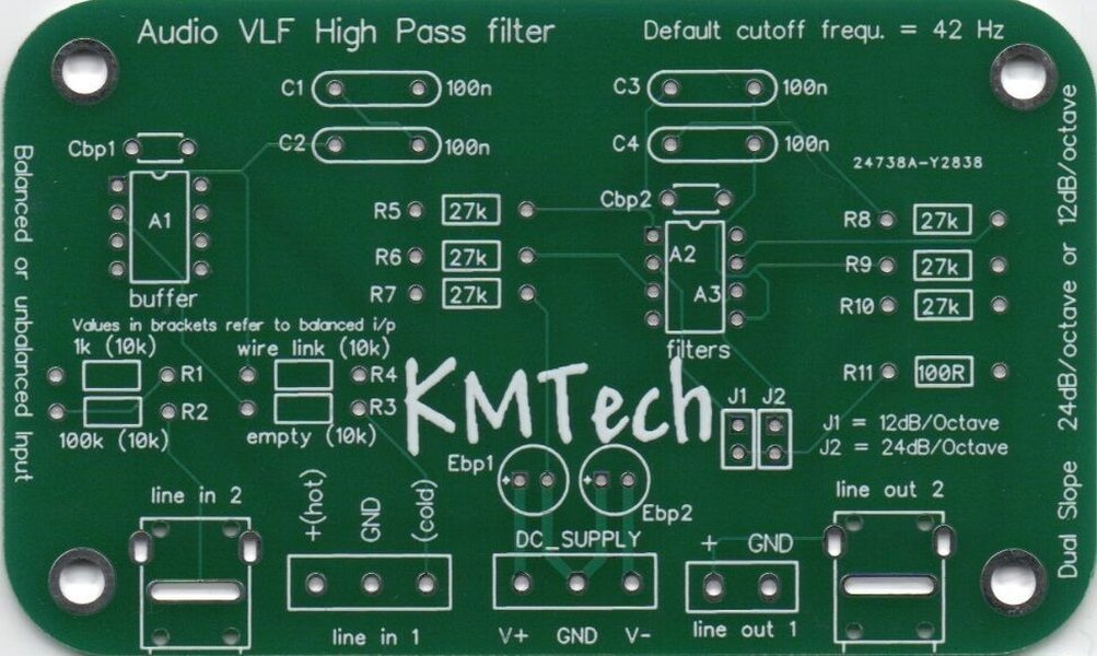
An example circuit board likely incorporating active components like op-amps.
Construction
These can be designed by adding an extra RC network to a first-order active high-pass filter or by using specific second-order topologies. Popular configurations include:
- Sallen-Key Topology: Known for its simplicity, using one op-amp, two resistors, and two capacitors. It's non-inverting.
- Multiple Feedback (MFB) Topology: Also uses one op-amp, but with a different arrangement of resistors and capacitors. It's typically an inverting configuration.
An example IC often used is the LM741 op-amp, though modern designs often use improved op-amps.
Characteristics
- Pros: Can provide signal gain, eliminates loading effects between stages due to the op-amp's high input impedance and low output impedance, allows for precise control over Q factor and cutoff frequency, can drive lower impedance loads.
- Cons: Requires a power supply, can introduce noise from the op-amp, has frequency limitations based on the op-amp's gain-bandwidth product, more complex than passive filters.
Cutoff Frequency Calculation (Sallen-Key Example)
For a common Sallen-Key high-pass filter design (often with C1=C2=C and R1=R2=R for simplicity or specific Q values), the cutoff frequency is given by:
\[ f_c = \frac{1}{2\pi \sqrt{R_1 R_2 C_1 C_2}} \]If \( R_1 = R_2 = R \) and \( C_1 = C_2 = C \), then:
\[ f_c = \frac{1}{2\pi RC} \]The gain and Q factor are determined by the ratios of resistors and capacitors within the specific topology.
Filter Characteristics Compared
This chart visually compares the key performance aspects of first-order versus second-order high-pass filters. Second-order filters generally offer superior performance in terms of selectivity and attenuation steepness, though often at the cost of increased complexity.
The chart highlights the significantly steeper roll-off and better frequency selectivity of second-order filters. While requiring more components and potentially being more complex to design, active second-order filters offer the advantage of gain.
Visualizing the Concepts
This mind map provides a structured overview of the key elements related to second-order high-pass filters, from their fundamental properties to their implementation and usage.
Design and Application Insights
The Design Process Simplified
Designing a second-order high-pass filter typically involves these steps:
- Define Specifications: Determine the required cutoff frequency (fc), desired passband gain (especially for active filters), and filter alignment (e.g., Butterworth for maximal flatness, Chebyshev for steeper roll-off with ripple, Bessel for linear phase).
- Select Topology: Choose between passive or active implementation. If active, select a suitable topology like Sallen-Key or MFB based on requirements (e.g., non-inverting vs. inverting, component sensitivity).
- Calculate Component Values: Use standard filter design equations, tables (for specific alignments like Butterworth), or design software/calculators to find appropriate resistor and capacitor values based on the chosen fc, Q, and gain. Normalised prototype designs (often based on 1 rad/s cutoff) are frequently used and then scaled to the target frequency and impedance.
- Simulate and Verify: Use circuit simulation software (like SPICE) to model the designed filter. Verify its frequency response (Bode plot), phase response, and transient behavior to ensure it meets the specifications. Build and test a prototype if necessary.
Butterworth Alignment: A Popular Choice
The Butterworth filter alignment is often chosen for second-order (and higher-order) filters when a maximally flat passband response is desired. This means there is no ripple or peaking in the range of frequencies that are intended to be passed. For a second-order high-pass Butterworth filter, the Q factor is specifically \(1/\sqrt{2} \approx 0.707\). Achieving this requires precise component value selection. Interestingly, a second-order high-pass Butterworth filter can often be designed by taking a second-order low-pass Butterworth design and interchanging the positions of the frequency-determining resistors and capacitors.
Passive vs. Active: Key Differences Summarized
Choosing between passive and active implementations depends heavily on the application's specific needs. This table summarizes the core trade-offs:
| Feature | Passive Second-Order HPF | Active Second-Order HPF |
|---|---|---|
| Core Components | Resistors, Capacitors (sometimes Inductors) | Op-Amp(s), Resistors, Capacitors |
| Roll-Off Rate | 40 dB/decade | 40 dB/decade |
| Signal Gain | No gain (typically loss/attenuation) | Can provide voltage gain |
| Loading Effect | Susceptible (especially when cascaded without buffering/scaling) | Mitigated by op-amp buffering |
| Power Supply | Not required | Required |
| Complexity | Simpler circuit | More complex circuit, requires power routing |
| Noise | Lower inherent noise (thermal noise from R) | Can add noise from the op-amp |
| Impedance | Input/output impedance depends on components | High input impedance, Low output impedance (defined by op-amp) |
Practical Implementations and Applications
Second-order high-pass filters are workhorses in electronics due to their enhanced filtering capabilities compared to first-order designs.
Common Uses Across Fields
- Audio Electronics: Removing subsonic rumble (frequencies below human hearing) from microphone or turntable inputs, implementing crossover networks in speakers (directing high frequencies to tweeters), eliminating DC offset in amplifier stages, and acting as basic tone controls or equalizers.
- Communications Systems: Filtering out low-frequency noise or DC components in signal paths, conditioning signals before transmission or after reception.
- Instrumentation and Measurement: Blocking slow DC drift or low-frequency interference in sensor readings, ensuring accurate measurement of higher-frequency phenomena.
- Control Systems: Attenuating low-frequency disturbances or noise that could affect system stability or performance.
- Power Electronics: Reducing low-frequency harmonics in power lines or within power supply circuits.
Visualizing Filter Action
The following video provides a helpful overview of implementing both passive and active second-order high-pass filters, illustrating the concepts discussed:
This video discusses the practical implementation of both passive and active second-order high-pass filters.
Higher-Order Filters
For even steeper roll-off rates and greater selectivity, filters of higher order (3rd, 4th, 5th, etc.) can be constructed. These are typically made by cascading first-order and second-order filter sections. Each additional order increases the roll-off rate by another 20 dB/decade. For example, a fourth-order filter (often made by cascading two second-order sections) would have a roll-off rate of 80 dB/decade.
Frequently Asked Questions (FAQ)
What exactly makes a high-pass filter "second-order"?
Why use a second-order filter instead of a simpler first-order one?
What is the significance of the Q factor in a second-order filter?
Can I build a second-order high-pass filter without an op-amp?
References
-
Active High Pass Filter - Electronics Tutorials
-
Passive High Pass Filter - Electronics Tutorials
- Active High Pass Filter. Types, Circuits & Calculations - Electrical Technology
- SECTION 3 Second Order Filters - Oregon State University
-
Sallen and Key Filter Design and Topology - Electronics Tutorials
- Designing of High Pass Filter - Engineers Garage
- Second Order High Pass Butterworth Filter - EEE Guide
Recommended
Last updated April 24, 2025