
Unlock the Power of the Sun: Expert Guide to Setting Up Six 200W Solar Panels Safely
A step-by-step journey into configuring your solar array with essential fuse and circuit breaker protection for optimal performance and safety.
Embarking on a solar power project with six 200-watt panels can be a rewarding endeavor, offering a substantial 1200 watts of potential energy. However, a safe and efficient setup hinges on meticulous planning, correct wiring, and the strategic placement of protective devices like fuses and circuit breakers. This guide will walk you through the intricacies of configuring your solar array, ensuring longevity and reliable operation.
Essential Insights: Key Takeaways
- Wiring Configuration is Crucial: For six 200W panels, a series-parallel configuration (e.g., two strings of three panels in series, with these strings then connected in parallel) is generally optimal for balancing voltage and current for most charge controllers.
- Overcurrent Protection is Non-Negotiable: DC-rated fuses and circuit breakers must be correctly sized and installed at specific points in the system (panel strings, array output, charge controller connections, battery, and inverter) to prevent damage from overcurrents or short circuits.
- Component Compatibility Matters: Ensure your charge controller, wiring, and battery bank are appropriately sized to handle the voltage and current produced by your 1200W solar array and the demands of your loads.
Understanding Your Solar System Components
Before diving into the installation, it's vital to understand the role of each component in your six-panel, 200W solar system.
Solar Panels: The Heart of Your System
You have six 200-watt solar panels, providing a total potential power output of 1200 watts. Typical specifications for a 200W panel might be:
- Voltage at Maximum Power (Vmp): Around 18-20 Volts DC
- Current at Maximum Power (Imp): Around 10-11 Amps DC
- Open Circuit Voltage (Voc): Around 22-24 Volts DC
- Short Circuit Current (Isc): Around 11-12 Amps DC
These values are critical for designing your wiring configuration and sizing your protection devices.
Wiring Configurations: Tailoring Voltage and Current
How you connect your panels significantly impacts the system's overall voltage and current.
Series Wiring
Connecting panels in series (positive of one to negative of the next) increases the voltage while keeping the current the same as a single panel. For example, three 20V panels in series would output 60V.
Parallel Wiring
Connecting panels in parallel (all positives together, all negatives together) increases the current while keeping the voltage the same as a single panel. For example, three 10A panels in parallel would output 30A.
Series-Parallel Wiring
For multiple panels, like your six 200W units, a series-parallel configuration is often the most practical. A common approach for six panels is to create two strings of three panels each wired in series. Then, these two series strings are connected in parallel. Let's assume each panel has Vmp ≈ 19V and Imp ≈ 10.5A (Isc ≈ 11A):
- Each string (3 panels in series):
- Voltage = 3 x 19V = 57V
- Current = 10.5A (Isc = 11A)
- Total array (2 strings in parallel):
- Voltage = 57V
- Current = 2 x 10.5A = 21A (Isc = 22A)
This configuration provides a moderate voltage (around 57V), which is suitable for many MPPT charge controllers and helps reduce resistive losses in wiring, while the total current (around 21A) is manageable.
Illustrative diagram showing basic series and parallel solar panel connections.
Fuses and Circuit Breakers: Your System's Guardians
Fuses and circuit breakers are critical safety devices. They protect your wiring and equipment from overcurrent conditions (due to faults, short circuits, or unexpected surges) that could lead to overheating, fire, or component damage. Always use DC-rated fuses and breakers specifically designed for solar PV applications, as AC devices may not perform correctly in DC circuits.
- Fuses: Contain a wire that melts and breaks the circuit when excessive current flows. They are single-use and must be replaced after blowing.
- Circuit Breakers: Automatically interrupt current flow when an overload or short circuit is detected. They can be reset manually, making them convenient for circuits that might occasionally trip.
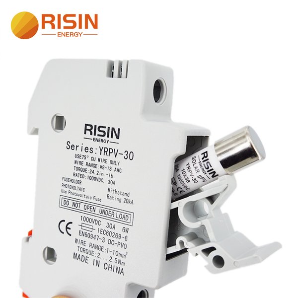
DC solar fuse holder (left) and DC circuit breaker (right), essential for system protection.
Other Essential Components
- Charge Controller: Regulates the power from the solar panels to charge the batteries efficiently and prevent overcharging. An MPPT (Maximum Power Point Tracking) controller is highly recommended for arrays like yours, as it can optimize power harvest, especially with higher panel string voltages. For a 1200W array, ensure your controller can handle the array's voltage (Voc) and current (Isc), as well as the power.
- Battery Bank: Stores the energy generated by your panels. The capacity (Amp-hours, Ah) and voltage (12V, 24V, 48V) must be chosen based on your energy needs and system design.
- Inverter (Optional): If you need to power AC appliances, an inverter converts DC power from the batteries to AC power. It should be sized according to your maximum AC load.
- Wiring and Connectors: Use appropriately sized copper wiring (e.g., 10 AWG for panel strings, potentially thicker for main runs) rated for outdoor/UV exposure. MC4 connectors are standard for secure, weatherproof connections between solar panels.
- Combiner Box: For systems with multiple parallel strings, a combiner box provides a tidy and safe way to join the strings and often houses string fuses or breakers.
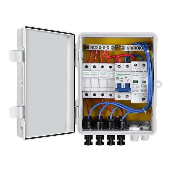
Example of a PV combiner box, useful for organizing parallel string connections and housing fuses.
Visualizing Wiring Configurations: A Comparative Look
The choice of wiring configuration impacts several aspects of your solar array's performance. The radar chart below compares three potential configurations for six 200W panels: full series (6S), full parallel (6P), and a series-parallel (2S3P - two strings of three panels in series, then strings in parallel) setup.
This chart illustrates that the Series-Parallel (2S3P) configuration offers a balanced profile, making it a strong candidate for your six 200W panels. It provides a good voltage level for MPPT charge controllers, manageable current, decent shading tolerance, and reasonable wiring complexity.
Step-by-Step Setup Guide for Six 200W Solar Panels
We will proceed with the recommended 2S3P (two strings of three panels in series, with the strings connected in parallel) configuration.
1. Planning and Design
Confirm Panel Specifications
Check the labels on your 200W panels for their exact Vmp, Imp, Voc, and Isc values. For our example, we'll use: Vmp ≈ 19V, Imp ≈ 10.5A, Voc ≈ 23V, Isc ≈ 11A.
Calculate Array Output (2S3P)
- One String (3 panels in series):
- Vmp_string = 3 x 19V = 57V
- Imp_string = 10.5A
- Voc_string = 3 x 23V = 69V (Ensure charge controller's max Voc input is higher)
- Isc_string = 11A
- Total Array (2 strings in parallel):
- Vmp_array = 57V
- Imp_array = 2 x 10.5A = 21A
- Voc_array = 69V
- Isc_array = 2 x 11A = 22A
- Total Power: 6 panels x 200W/panel = 1200W (or 57V x 21A = 1197W)
2. Mounting the Panels
Securely mount your solar panels in a location that receives maximum direct sunlight throughout the day, ideally facing south in the Northern Hemisphere or north in the Southern Hemisphere. Ensure the mounting structure is robust and can withstand local weather conditions.
3. Wiring the Solar Panels
Wire String 1 (3 Panels in Series)
Connect the positive (+) terminal of Panel 1 to the negative (-) terminal of Panel 2. Then, connect the positive (+) terminal of Panel 2 to the negative (-) terminal of Panel 3. The remaining open negative (-) terminal of Panel 1 and the open positive (+) terminal of Panel 3 are the outputs for String 1.
Wire String 2 (3 Panels in Series)
Repeat the same series wiring process for Panels 4, 5, and 6 to create String 2.
Connect Strings in Parallel (Using a Combiner Box or Y-Branch Connectors)
A combiner box is recommended for a clean and safe installation.
- Run the positive and negative output wires from String 1 to the combiner box.
- Run the positive and negative output wires from String 2 to the combiner box.
- Inside the combiner box, connect the positive output of String 1 to the positive output of String 2.
- Similarly, connect the negative output of String 1 to the negative output of String 2.
4. Installing Fuses and Circuit Breakers
This is a critical step for safety. The general rule for sizing fuses/breakers is 1.25 to 1.56 times the short-circuit current (Isc) of the circuit they are protecting. Always round up to the next standard fuse/breaker size.
String Fuses/Breakers (Protecting each parallel string)
- Location: On the positive wire of each series string, ideally within the combiner box before the strings are paralleled.
- Purpose: Protects individual strings and their wiring from overcurrent, and prevents a faulty string from drawing current from healthy strings. Required when three or more strings are in parallel; good practice for two strings as well.
- Sizing: Isc_string = 11A. Fuse/Breaker = 1.25 x 11A = 13.75A. Use a 15A DC fuse or breaker for each string.
Array Disconnect / PV Breaker (Between Combiner Box and Charge Controller)
- Location: On the positive wire running from the combiner box output to the charge controller's PV input.
- Purpose: Protects the wiring to the charge controller and the charge controller itself from array faults. Also serves as a means to disconnect the array.
- Sizing: Isc_array = 22A. Breaker = 1.25 x 22A = 27.5A. Use a 30A DC circuit breaker.
Charge Controller to Battery Bank Breaker
- Location: On the positive wire between the charge controller's battery output and the positive terminal of the battery bank.
- Purpose: Protects wiring and the charge controller from battery faults, and the battery from controller faults.
- Sizing: This depends on the charge controller's maximum output current and the battery bank voltage. For a 1200W array feeding an MPPT controller connected to a 24V battery system: Max current ≈ 1200W / 24V = 50A. Breaker = 1.25 x 50A = 62.5A. Use a 60A or 70A DC circuit breaker. (If using a 12V battery system, this current would be ~100A, requiring a ~125A breaker).
Battery Bank to Inverter Fuse/Breaker (If using an inverter)
- Location: On the positive wire between the battery bank and the inverter's DC input.
- Purpose: Protects the high-current wiring to the inverter and the inverter itself from short circuits or overloads. This is a critical fuse.
- Sizing: Depends on the inverter's maximum continuous power draw. For a 2000W inverter on a 24V system: Max current = 2000W / 24V (nominal battery voltage) ≈ 83.3A. Fuse/Breaker = 1.25 x 83.3A ≈ 104A. Use a 100A or 125A DC fuse or breaker.
5. Connecting to the Charge Controller
Connect the output from the PV array (from the 30A array disconnect breaker) to the PV input terminals on your MPPT charge controller. Ensure correct polarity (+ to +, - to -).
6. Connecting to the Battery Bank
Connect the battery output terminals of your charge controller (through the appropriately sized breaker, e.g., 60A for a 24V system) to your battery bank. Connect positive to positive and negative to negative. It is generally recommended to connect the battery to the charge controller BEFORE connecting the solar panels.
7. Connecting the Inverter (If Applicable)
Connect your inverter to the battery bank, ensuring the appropriately sized fuse/breaker (e.g., 100A-125A for a 2000W/24V inverter) is in the positive line as close to the battery as possible. Follow the inverter manufacturer's instructions carefully.
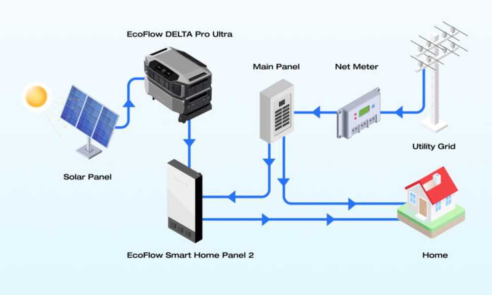
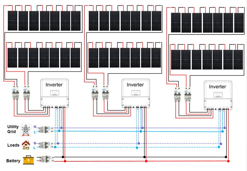
General solar system wiring diagram, illustrating the flow from panels to loads.
System Overview: A Mindmap of Connections
The following mindmap visualizes the key components of your six-panel solar system and the placement of protective fuses and breakers. This helps in understanding the overall architecture and critical safety points.
This mindmap highlights how each component connects and where overcurrent protection devices are strategically placed to ensure safety and proper functioning of your solar installation.
Summary of Fuse and Breaker Placement
The table below summarizes the recommended locations and sizes for fuses and circuit breakers in your six 200W solar panel system, assuming a 2S3P configuration and a 24V battery system with a 2000W inverter.
| Location | Device Type | Recommended Size (DC-Rated) | Purpose |
|---|---|---|---|
| Each Solar Panel String (Positive line, in combiner box) | Fuse or Circuit Breaker | 15A | Protects individual string wiring; isolates faulty strings. (Based on ~11A Isc per string, 1.25x rule) |
| Combiner Box Output to Charge Controller (PV Main Disconnect) | Circuit Breaker | 30A | Protects main PV wiring to charge controller and controller input. (Based on ~22A total array Isc, 1.25x rule) |
| Charge Controller Output to Battery Bank | Circuit Breaker | 60A (for 24V system, ~50A controller output) | Protects wiring and controller/battery from faults. (Based on controller's max output current, 1.25x rule) |
| Battery Bank to Inverter | Fuse or Circuit Breaker | 100A - 125A (for 2000W, 24V inverter) | Protects high-current wiring and inverter. (Based on inverter's max DC draw, 1.25x rule) |
| DC Load Circuits (if any, from battery or load output of controller) | Fuse or Circuit Breaker | Sized per load (e.g., 10A, 20A) | Protects individual DC load circuits. |
Note: Always verify these sizes against your specific component specifications and local electrical codes. The 1.25x multiplier for Isc is a common rule of thumb; some standards may recommend up to 1.56x.
Wiring Solar Panels: Series-Parallel Explained
Understanding how to wire panels in a series-parallel configuration is key for larger arrays. This video provides a helpful visual explanation of the concept:
This video, "How to Wire Solar Panels in Series Parallel," demonstrates the technique of creating strings of panels in series and then connecting those strings in parallel, which is precisely the method recommended for your six 200W panels. It clarifies how this affects voltage and current, crucial for matching your array to your charge controller.
Safety First: Essential Precautions
- Work Safely: Always de-energize circuits before working on them. Cover solar panels with an opaque material to stop electricity production during installation. Wear appropriate personal protective equipment (PPE), including insulated gloves and eye protection.
- Use DC-Rated Components: Ensure all fuses, breakers, switches, and wiring are rated for DC use and for the specific voltages and currents in your system.
- Correct Wire Sizing: Use wire gauges appropriate for the current they will carry and the length of the run to prevent overheating and voltage drop. Consult ampacity charts. Typically, 10 AWG copper wire is suitable for currents up to 30A in solar applications, but longer runs or higher currents will require thicker wire.
- Proper Grounding: All metallic components of the solar system, including panel frames, mounting racks, and equipment enclosures, should be properly grounded according to local electrical codes to prevent shock hazards.
- Follow Manufacturer Instructions: Adhere to the installation manuals for all components (panels, charge controller, inverter, etc.).
- Local Codes and Permits: Check with your local authorities regarding electrical codes, permits, and inspection requirements for solar installations.
- Professional Help: If you are unsure about any aspect of the installation, especially the electrical wiring, consult a qualified electrician or solar installer.
Frequently Asked Questions (FAQ)
Conclusion
Setting up six 200-watt solar panels involves more than just connecting wires; it requires a thoughtful approach to system design, wiring configuration, and, most importantly, safety through proper fusing and circuit protection. By adopting a series-parallel configuration like the 2S3P discussed, and by correctly sizing and placing DC-rated fuses and circuit breakers, you can create a robust, efficient, and safe solar power system. Remember to always prioritize safety, adhere to electrical codes, and consult with professionals if you have any doubts. Your well-planned solar installation will provide clean energy for years to come.
Recommended Further Exploration
- How do I calculate and minimize voltage drop in my solar panel wiring for long distances?
- What are the best battery types and capacities for a 1200W off-grid solar system?
- What are the essential grounding techniques for a residential solar panel installation to ensure safety?
- How can I effectively monitor my solar panel system's performance and troubleshoot common issues?
Referenced Search Results
 amazon.com