
Designing the Solar Cruiser: Efficiency Meets Versatility
Unveiling a conceptual solar vehicle balancing aerodynamics, weight, and flexible passenger capacity.
Key Design Highlights
- Ultra-Efficient Aerodynamics: Utilizing a streamlined teardrop shape to achieve an exceptionally low drag coefficient, minimizing energy consumption.
- Lightweight Yet Robust Construction: Employing advanced materials like carbon fiber composites and aluminum alloys to reduce weight without compromising structural integrity or safety.
- Flexible Seating Configuration: Offering a modular interior design capable of comfortably accommodating 2 to 5 passengers, adapting to various needs.
Introducing the "Solar Cruiser" Concept
Philosophy and Core Features
The Solar Cruiser represents a conceptual leap towards sustainable personal transportation, meticulously designed to meet stringent requirements for efficiency, minimal weight, superior aerodynamics, and adaptable passenger capacity (2-5 seats). Drawing inspiration from leading solar vehicle projects and aerodynamic principles, the core philosophy integrates cutting-edge technology with practical usability. The design prioritizes maximizing energy harvest from integrated solar panels while minimizing energy expenditure through advanced aerodynamics and lightweight construction.
This vehicle is envisioned not just as a technological showcase but as a potentially viable option for eco-conscious commuting, blending race-proven efficiency strategies with the necessities of everyday use. It aims to operate significantly on direct solar power for daily driving needs, supplemented by an efficient battery storage system for extended range and operation during low-light conditions.
Mastering Aerodynamics: The Key to Efficiency
Shaping the Flow
Aerodynamic efficiency is paramount in solar vehicle design due to the limited power available from solar panels. The Solar Cruiser's external geometry is dictated by the need to minimize air resistance (drag).
The Teardrop Principle
The fundamental shape adopted is an elongated teardrop or airfoil profile. This form is naturally streamlined, allowing air to flow smoothly over the vehicle's surface with minimal disturbance. It promotes laminar flow (smooth layers of air) and delays flow separation, significantly reducing pressure drag, which is the dominant form of resistance at typical driving speeds.
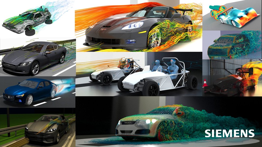
Computer simulation illustrating airflow patterns around different vehicle shapes, highlighting aerodynamic efficiency.
Minimizing Frontal Area
The vehicle features a narrow front profile and a low-slung stance. Reducing the frontal area directly decreases the amount of air the vehicle must push aside, further lowering drag forces. This is balanced against the need for sufficient interior space and adequate surface area for solar panels.
Smooth Surfaces and Integrated Features
All surfaces are designed to be exceptionally smooth, eliminating protrusions that could create turbulence. Features like door handles might be flush-mounted, and panel gaps minimized. Wheel wells can be partially or fully covered (fairings) to smooth airflow around the wheels, a significant source of drag on conventional vehicles.
Underbody Management
The underbody is designed to be as flat and smooth as possible. This prevents air from becoming trapped and creating turbulence underneath the car. A slight upward slope towards the rear (diffuser effect) can help manage airflow separation and potentially reduce lift or even generate downforce for improved stability.
Core Components and Construction
Integrating Efficiency and Lightweight Design
The selection and integration of components are crucial for achieving the design goals. Emphasis is placed on high efficiency and low weight for every part of the vehicle.
Key Component Breakdown
The following table summarizes the essential components of the Solar Cruiser, their materials, and their contribution to the overall design objectives:
| Component | Material/Type | Function & Design Consideration |
|---|---|---|
| Chassis/Frame | Aluminum Alloy or Carbon Fiber Monocoque | Provides structural integrity. Lightweight materials are critical for reducing overall mass (target < 300kg). Design integrates mounting points for all other components and ensures passenger safety. |
| Body Shell | Carbon Fiber Composites | Forms the aerodynamic outer shape. Must be lightweight, strong, and smooth. Designed for minimal drag and maximum solar panel integration. |
| Solar Array | High-Efficiency Monocrystalline or Multijunction PV Cells | Covers a significant portion of the upper surface (roof, hood). Converts sunlight directly into electricity. Placement optimized to avoid shading and maximize exposure (~4-5 m² area). |
| Battery Pack | Lithium-ion (High Energy Density) | Stores energy from solar panels and potential grid charging. Located low and centrally for optimal weight distribution and stability. Sized for target range and power demands. |
| Electric Motor(s) | High-Efficiency Brushless DC Hub or In-wheel Motors | Provides propulsion. Chosen for high power-to-weight ratio and efficiency (>95%). Rear-wheel or potentially all-wheel drive configuration. |
| Wheels & Tires | Lightweight Alloy Wheels, Low Rolling Resistance Tires | Minimize rotational inertia and friction with the road surface. Narrow tire profile reduces aerodynamic drag and rolling resistance. |
| Suspension | Lightweight Aluminum Components, Double Wishbone or similar | Provides ride comfort and handling stability while minimizing weight. Tuned for low ride height to enhance aerodynamics. |
| Steering & Brakes | Lightweight Rack-and-Pinion Steering, Regenerative Braking System | Ensures precise control. Regenerative braking recovers kinetic energy during deceleration, improving overall efficiency. |
| Control System (ECU/BMS) | Microcontroller-based system | Manages power flow between solar panels, battery, and motor (Maximum Power Point Tracking - MPPT), optimizes energy usage, monitors battery health (BMS). |
| Interior & Seating | Lightweight Composite Seats, Minimalist Trim | Modular design allows seating for 2 to 5 occupants. Focus on weight reduction and ergonomics within the streamlined body shape. |
Visualizing the Interconnected Design Elements
A Mindmap of Solar Vehicle Design Priorities
Understanding how different aspects of solar vehicle design influence each other is crucial. This mindmap illustrates the relationships between the core requirements and the engineering solutions employed in the Solar Cruiser concept.
Conceptual Layout: Visual Description
Imagining the Solar Cruiser Views
As generating precise technical drawings requires specialized tools, the following sections provide detailed textual descriptions of black-and-white conceptual sketches, outlining the Solar Cruiser's layout from different perspectives.
Top View Sketch Description
Imagine an overhead view. The dominant shape is an elongated teardrop, wide near the front third and tapering smoothly towards a pointed rear. The largest surface area, the roof extending partially onto the hood and rear deck, is covered by a grid pattern representing the solar panel array. The cockpit canopy or windshield area appears as a curved, slightly darker shape near the front. Four wheels are visible, positioned relatively wide apart for stability, possibly slightly inset within the bodywork outline. Dashed lines within the cabin area suggest the adaptable seating layout: two distinct front seats and a rear bench area marked to indicate space for up to three additional, smaller seats or flexible cargo space.
Side View Sketch Description
From the side, the Solar Cruiser presents a very low profile. The vehicle almost hugs the ground, with minimal ground clearance. The characteristic teardrop shape is evident, with a smoothly arching roofline that peaks above the front seats and slopes gently downwards towards the rear tail. The nose is low and rounded, flowing seamlessly into the steeply raked windshield. The wheels are proportionally large but narrow, with the rear wheel potentially partially covered by an aerodynamic spat or fairing integrated into the bodywork. The side windows follow the roofline's curve, tapering towards the back. Subtle lines might indicate door seams, designed to be flush with the body. The overall impression is one of extreme streamlining and length relative to height (dimensions roughly 4.5-5m long, 1.2-1.4m high).
Front View Sketch Description
Looking head-on, the Solar Cruiser appears wide and low, emphasizing its aerodynamic focus. The frontal area is minimized. The shape is rounded, perhaps slightly V-shaped at the very bottom edge to manage airflow. The width is primarily defined by the track of the front wheels, which might be enclosed within curved bodywork. The windshield curves both upwards and side-to-side. The hood area slopes downwards towards the nose and is visibly covered with the solar panel grid pattern. There are no traditional grilles; necessary cooling inlets would be small, strategically placed, and smoothly integrated. Headlights would be narrow LED strips conforming to the body shape.
Simulating Aerodynamic Performance
Computational Fluid Dynamics (CFD) Insights
Computational Fluid Dynamics (CFD) is a critical tool in designing low-drag vehicles. A simulation for the Solar Cruiser would analyze how air flows around its proposed body shape.
Expected CFD Simulation Results (Description)
A CFD simulation visualization would typically show the vehicle body outline immersed in a field of colors and lines representing airflow characteristics. For the Solar Cruiser's teardrop shape:
- Streamlines: Thin lines flowing around the body would be mostly smooth and attached to the surface, indicating laminar flow. Minimal divergence or swirling patterns, especially towards the rear, would signify low turbulence and reduced drag.
- Pressure Contours: Colors would indicate pressure zones. High pressure (often shown in warmer colors like red/yellow) would be expected at the very front stagnation point. Lower pressure (cooler colors like blue/green) would dominate the upper surfaces and sides, contributing to lift characteristics (which should be minimal or slightly negative/downforce for stability). The wake region directly behind the vehicle would show a relatively small area of low pressure compared to less aerodynamic shapes.
- Velocity Vectors: Small arrows could show the speed and direction of air at various points. These would confirm smooth acceleration of air over the curved surfaces and a relatively undisturbed flow pattern behind the vehicle.
- Drag Coefficient (Cd): The simulation would calculate a numerical value for the drag coefficient. For this design, the target would be exceptionally low, likely aiming for a Cd between 0.15 and 0.20, significantly better than typical passenger cars (Cd ~0.25-0.35).
The overall result would visually confirm the effectiveness of the teardrop shape, minimized frontal area, and smooth surfaces in reducing air resistance, a key factor for maximizing the vehicle's range and efficiency on solar power.

Example of CFD visualization showing surface streamlines, indicating smooth airflow over a solar car body.
Balancing Design Priorities
A Comparative Look at Key Factors
Designing a solar vehicle involves balancing competing priorities. This chart provides a conceptual representation of how the Solar Cruiser design prioritizes various factors compared to a conventional electric vehicle (EV) and a dedicated solar racing car. Higher scores indicate greater emphasis or performance in that area.
This comparison highlights the Solar Cruiser's strong focus on aerodynamics, weight, and solar capture, similar to racers, but with a necessary compromise to achieve greater passenger versatility and practicality, moving it partially towards the characteristics of a conventional EV, albeit with different cost and range profiles.
Insights into Solar Car Design Principles
Aerodynamics and Weight Explained
Understanding the fundamental challenges and solutions in solar car design provides valuable context for the Solar Cruiser concept. This video delves into the critical importance of aerodynamics and lightweight construction, explaining how engineers approach these challenges when building competitive or practical solar vehicles.
The video emphasizes the trade-offs involved, such as balancing the need for a large surface area for solar panels against the aerodynamic penalties of increased size. It also touches upon material science and structural design techniques used to minimize mass while maintaining safety and durability – principles directly applied in the conceptual Solar Cruiser.
Frequently Asked Questions (FAQ)
How realistic is a 2-5 seat solar car?
Can a solar car run entirely on the sun?
Why is the teardrop shape so important for aerodynamics?
What are the main challenges in building solar cars?
References
- Aerodynamics of a Solar Car | Ansys Innovation Courses - Ansys Innovation Space
- Solar car - Wikipedia
- Solar Car - Gurit
- Aptera Motors - Aptera
- How Solar Vehicles Work: A Deep Dive — Sustainable Review
- 9 Solar Vehicle Designs That Could Transform the Clean Energy Landscape - mycarmakesnoise.com
- Solar Car Design for Maximum Efficiency - Solar Car Club
Recommended Reading
 scientificgems.wordpress.com
Last updated April 15, 2025