
Comprehensive Overview of Solid Modeling Techniques
Exploring CSG, Feature-Based, Box, Modular, and Assembly Modeling
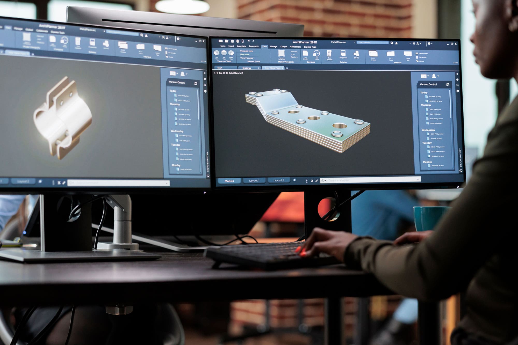
Highlights
- CSG uses Boolean operations on simple primitives for precise, mathematically defined models.
- Feature-Based Modeling builds complex parts with a history of parametric design features for ease of modification.
- Box, Modular, and Assembly Modeling offer intuitive, component-driven processes that support everything from early sculpting to full system integration.
1. Constructive Solid Geometry (CSG)
Fundamentals of CSG
Constructive Solid Geometry (CSG) is a solid modeling technique that builds complex shapes by combining simpler, well-defined geometric primitives using Boolean operations. These primitives typically include cubes, spheres, cylinders, cones, and other basic solids.
Boolean Operations
The core of CSG lies in Boolean operations:
- Union: Merges two or more primitives to form a single solid where all volumes are combined.
- Intersection: Retains the common volume shared by the overlapping primitives.
- Difference: Subtracts the volume of one primitive from another, effectively “carving out” material.
In many computer-aided design (CAD) systems, CSG models are organized through binary trees where the leaves represent primitive solids and the nodes represent the Boolean operations applied. This allows designers to modify or update the model by simply changing a node’s associated operation or its input primitives, making CSG a powerful tool for iterative design processes.
CSG proves particularly beneficial in scenarios requiring high geometric precision, such as engineering design and manufacturing, where the mathematically defined nature of the operations ensures accurate measurements and fits for components. Additionally, CSG models are well-suited for simulations and analyses in physical environments.
2. Feature-Based Modeling
Concept and Structure
Feature-based modeling is a technique rooted in a parametric approach, where the model is constructed step-by-step through the addition and manipulation of features. Rather than building a model by explicitly defining all surfaces and edges from scratch, designers add features such as extrusions, cuts, fillets, and holes that represent manufacturing or functional elements.
Defining Features
Features in this process are predefined elements that carry both geometric and non-geometric information. For instance:
- Extrusions: Create a volume by extending a shape in a specific direction.
- Cuts or Holes: Remove material from a solid, with the operation often propagating changes automatically if the base geometry is altered.
- Fillets and Chamfers: Smooth or bevel sharp edges for both aesthetic and functional purposes.
The history and parameters associated with each feature are maintained in a feature tree. This structured record of operations allows designers to revisit and modify earlier steps without needing to rebuild the entire model. Such parametric and feature-driven design is crucial in mechanical and industrial applications, where revisions and modifications are frequent during the product development cycle.
Feature-based modeling is widely implemented in software like SolidWorks, CATIA, and Autodesk Inventor, where the ability to easily modify features is key to streamlining design iterations and ensuring that any changes in one part of the model automatically update related features.
3. Box Modeling
Technique and Workflow
Box modeling is a 3D modeling technique that starts with a simple shape—typically a cube or “box”—and progressively refines it into a complex model through various forms of manipulation. It is especially popular in character modeling, game asset creation, and overall architectural modeling due to its intuitive workflow.
Step-by-Step Process
The process generally consists of:
- Initial Creation: Begin with a basic geometric shape such as a cube or other simple polyhedron.
- Subdivision: Subdivide the initial shape to increase the number of faces, edges, and vertices, allowing for more detailed manipulations.
- Manipulation: Adjust and extrude vertices, edges, or faces to sculpt the desired form. This includes stretching, tapering, and smoothing sections.
- Refinement: Iteratively refine topological details to ensure the model sustains a clean mesh and proper geometry throughout.
Box modeling is particularly valued for its flexibility and ease of use; artists can quickly establish the overall form of a model and then work on adding finer details incrementally.
In applications such as animation and game development, the quality of the mesh topology is key to ensuring that textures, deformations, and lighting render correctly. Thus, box modeling provides an excellent starting point for complex organic shapes like characters and creatures.
4. Modular Modeling
Developing Models in Modules
Modular modeling involves breaking down a large or complex model into smaller, interchangeable components or modules. Each module is a standalone unit that can be developed, tested, and refined independently before being combined into the overall design.
Modularity and Reuse
This method is particularly effective in enhancing collaboration among teams, as different designers or engineers can focus on distinct modules without interfering with the entire project. Key aspects include:
- Component Independence: Modules are designed as independent units that represent specific functions or areas within the overall product.
- Interchangeability: Components can be easily replaced, updated, or recycled across different projects, saving time and ensuring consistency.
- Streamlined Collaboration: In large projects, modular modeling allows multiple teams to work on different subsystems simultaneously.
Industries such as automotive design, electronics, and architecture benefit greatly from modular modeling. For example, in automotive design, various modules like the engine bay, chassis, and interior components can be independently developed before integrating them into the final assembly.
Additionally, this technique supports scalability; as new features are conceived, they can be added as separate modules without necessitating a complete overhaul of the existing design.
5. Assembly Modeling
Integrating Components into Systems
Assembly modeling is the process of creating a complete system by integrating multiple individual parts or modules. The focus is on how these parts fit together, interact, and function collectively within a larger assembly. This is a crucial stage in product design, especially in industries like mechanical engineering, aerospace, and consumer electronics.
Approaches to Assembly Modeling
Assembly modeling typically follows two complementary approaches:
- Bottom-Up Assembly: Individual parts are designed separately and later integrated into an assembly. This method relies on pre-made components that are combined to build the final product.
- Top-Down Assembly: The overall assembly is designed first, and then individual components are created within the context of the assembly. This approach allows for components to be designed with an inherent understanding of system-level constraints and relationships.
In both cases, assembly modeling captures the relationships between parts using mating constraints—such as alignments, joints, and contact points—to ensure proper fit, function, and movement. Many modern CAD systems manage complex assemblies by allowing designers to apply these constraints and simulate mechanical fits before any physical prototypes are produced.
Assembly modeling not only checks for compatibility between components but also aids in identifying potential interference or clearance issues. This preemptive verification is particularly beneficial in mechanical systems and electronics, where small misalignments can lead to operational failures or manufacturing hassles.
Comparative Overview Table
| Technique | Core Principle | Primary Applications |
|---|---|---|
| Constructive Solid Geometry (CSG) | Boolean operations on primitives | Engineering CAD, precise prototyping |
| Feature-Based Modeling | Parametric features and history tree | Mechanical design, product development |
| Box Modeling | Iterative refinement from a basic box | Character modeling, game assets, visual effects |
| Modular Modeling | Breaking down a model into reusable modules | Large system design, architecture, collaborative projects |
| Assembly Modeling | Integrating separate parts with defined constraints | Product assembly, complex machinery, system integration |
In-Depth Analysis and Applications
Integrating Techniques for Comprehensive Design
Although each of these solid modeling techniques serves a distinct purpose, many real-world projects benefit from a hybrid approach that integrates several methods. For example, an engineering team might use CSG techniques to generate the base geometry of a component and then apply feature-based operations to add functional details such as holes and fillets. Once each component is fully developed, assembly modeling becomes critical to ensure that these individual parts fit together correctly.
In fields such as automotive or aerospace design, modular modeling complements assembly modeling by allowing different teams to develop specific sections—like the engine module, the body shell, or the electronic systems—independently. Later, these modules are assembled within a larger framework, with precise mating and alignment constraints ensuring that the system functions seamlessly as a whole.
Box modeling, primarily used in artistic and entertainment realms, also finds its niche in preliminary design phases where the silhouette and overall form of a model are more important than minute details. Designers can quickly sketch out the volume and proportions of a new character or product before moving to more sophisticated, detailed operations that might employ feature-based techniques.
The integration of these modeling approaches facilitates not only rapid prototyping but also iterative refinement. For instance, a designer who starts with a basic CSG model may later identify the need for additional detail and switch to feature-based modeling. In large-scale projects, the modular structure ensures that changes in one section do not necessitate reworking the entire model—a key advantage in complex, multidisciplinary design environments.
Additionally, modern CAD software often provides support for switching between or combining different modeling paradigms. This capability helps streamline workflows and enhance flexibility, allowing engineers and designers to take advantage of the strengths of each technique while mitigating their individual limitations.
References
- Box Modeling - Wikipedia
- Constructive Solid Geometry - Wikipedia
- Feature-Based Modeling - Machine Design
- Assembly Modeling - PTC
- Modular Modeling - Simulistics
Recommended Queries for Further Exploration
 static.sdcpublications.com
Last updated March 20, 2025