
Instantiating SystemVerilog Modules with AXI Interface and Modport
A Comprehensive Guide to AXI Interface Implementation in SystemVerilog
Key Takeaways
- Modular Design: Utilizing SystemVerilog interfaces and modports promotes cleaner and more maintainable code, especially for complex protocols like AXI.
- Signal Directionality: Properly defining modports ensures correct signal directions between master and slave modules, reducing connectivity errors.
- Reusability and Scalability: Interfaces encapsulate related signals, making them reusable across multiple modules and adaptable to protocol changes.
Introduction to AXI Interface in SystemVerilog
The Advanced eXtensible Interface (AXI) is a widely adopted interface protocol used in System-on-Chip (SoC) designs. It facilitates high-performance, high-frequency system designs by providing a flexible, pipelined communication structure between components. Implementing AXI interfaces in SystemVerilog using interfaces and modports enhances code modularity, readability, and reusability.
Defining the AXI Interface
To begin, an AXI interface encapsulates all the necessary signals required for AXI transactions. This encapsulation not only organizes the signal definitions but also simplifies the connection between different modules. Below is an example of defining an AXI interface with modports for master and slave roles.
AXI Interface Definition
interface AXI_Interface #(parameter ADDR_WIDTH = 32, DATA_WIDTH = 64) (
    input logic aclk,
    input logic aresetn
);
    // Write Address Channel
    logic [ADDR_WIDTH-1:0] awaddr;
    logic [7:0]            awlen;
    logic                  awvalid;
    logic                  awready;

    // Write Data Channel
    logic [DATA_WIDTH-1:0] wdata;
    logic [(DATA_WIDTH/8)-1:0] wstrb;
    logic                  wlast;
    logic                  wvalid;
    logic                  wready;

    // Write Response Channel
    logic [1:0]            bresp;
    logic                  bvalid;
    logic                  bready;

    // Read Address Channel
    logic [ADDR_WIDTH-1:0] araddr;
    logic [7:0]            arlen;
    logic                  arvalid;
    logic                  arready;

    // Read Data Channel
    logic [DATA_WIDTH-1:0] rdata;
    logic [1:0]            rresp;
    logic                  rlast;
    logic                  rvalid;
    logic                  rready;

    // Modport for Master
    modport master (
        input aclk, aresetn,
        output awaddr, awlen, awvalid,
        input awready,
        output wdata, wstrb, wlast, wvalid,
        input wready,
        input bresp, bvalid,
        output bready,
        output araddr, arlen, arvalid,
        input arready,
        input rdata, rresp, rvalid,
        output rready
    );

    // Modport for Slave
    modport slave (
        input aclk, aresetn,
        input awaddr, awlen, awvalid,
        output awready,
        input wdata, wstrb, wlast, wvalid,
        output wready,
        output bresp, bvalid,
        input bready,
        input araddr, arlen, arvalid,
        output arready,
        output rdata, rresp, rvalid,
        input rready
    );
endinterface
Implementing Master and Slave Modules
With the AXI interface defined, the next step is to implement the master and slave modules that will utilize this interface. These modules will interact through the defined modports, ensuring proper signal directionality and communication.
AXI Master Module
module AXI_Master #(parameter ADDR_WIDTH = 32, DATA_WIDTH = 64) (
    AXI_Interface.master axi
);
    // Master logic implementation
    always_ff @(posedge axi.aclk or negedge axi.aresetn) begin
        if (!axi.aresetn) begin
            axi.awvalid <= 1'b0;
            axi.wvalid  <= 1'b0;
            axi.bready  <= 1'b0;
            axi.arvalid <= 1'b0;
            axi.rready  <= 1'b0;
        end
        else begin
            // Example Write Address Channel Transaction
            axi.awaddr  <= 32'h00001000;
            axi.awlen   <= 8'h04;
            axi.awvalid <= 1'b1;

            // Example Write Data Channel Transaction
            axi.wdata   <= 64'hDEADBEEFCAFEBABE;
            axi.wstrb   <= 8'hFF;
            axi.wlast   <= 1'b1;
            axi.wvalid  <= 1'b1;

            // Example Read Address Channel Transaction
            axi.araddr  <= 32'h00002000;
            axi.arlen   <= 8'h04;
            axi.arvalid <= 1'b1;

            // Ready to receive read data
            axi.rready  <= 1'b1;
        end
    end
endmodule
AXI Slave Module
module AXI_Slave #(parameter ADDR_WIDTH = 32, DATA_WIDTH = 64) (
    AXI_Interface.slave axi
);
    // Slave logic implementation
    always_ff @(posedge axi.aclk or negedge axi.aresetn) begin
        if (!axi.aresetn) begin
            axi.awready <= 1'b0;
            axi.wready  <= 1'b0;
            axi.bvalid  <= 1'b0;
            axi.arready <= 1'b0;
            axi.rvalid  <= 1'b0;
            axi.rdata   <= {DATA_WIDTH{1'b0}};
        end
        else begin
            // Handle Write Address Handshake
            if (axi.awvalid && !axi.awready) begin
                axi.awready <= 1'b1;
            end else begin
                axi.awready <= 1'b0;
            end

            // Handle Write Data Handshake
            if (axi.wvalid && !axi.wready) begin
                axi.wready <= 1'b1;
            end else begin
                axi.wready <= 1'b0;
            end

            // Issue Write Response
            if (axi.wready && axi.wvalid) begin
                axi.bvalid <= 1'b1;
                axi.bresp  <= 2'b00; // OKAY response
            end else if (axi.bready && axi.bvalid) begin
                axi.bvalid <= 1'b0;
            end

            // Handle Read Address Handshake
            if (axi.arvalid && !axi.arready) begin
                axi.arready <= 1'b1;
            end else begin
                axi.arready <= 1'b0;
            end

            // Provide Read Data
            if (axi.arready && axi.arvalid) begin
                axi.rdata  <= 64'h123456789ABCDEF0;
                axi.rvalid <= 1'b1;
                axi.rresp  <= 2'b00; // OKAY response
            end else if (axi.rready && axi.rvalid) begin
                axi.rvalid <= 1'b0;
            end
        end
    end
endmodule
Top-Level Module Instantiation
The top-level module orchestrates the instantiation and connection of the AXI interface, master, and slave modules. It also manages clock and reset signals essential for synchronous operations.
Top-Level Module
module Top_Module;
    // Instantiate AXI Interface with parameters
    AXI_Interface #(
        .ADDR_WIDTH(32),
        .DATA_WIDTH(64)
    ) axi_if (
        .aclk(aclk),
        .aresetn(aresetn)
    );

    // Instantiate Master and Slave Modules
    AXI_Master #(
        .ADDR_WIDTH(32),
        .DATA_WIDTH(64)
    ) master_inst (
        .axi(axi_if.master)
    );

    AXI_Slave #(
        .ADDR_WIDTH(32),
        .DATA_WIDTH(64)
    ) slave_inst (
        .axi(axi_if.slave)
    );

    // Clock Generation
    initial begin
        aclk = 0;
        forever #5 aclk = ~aclk; // 100MHz Clock
    end

    // Reset Generation
    initial begin
        aresetn = 0;
        #15 aresetn = 1; // Release reset after 15 time units
    end
endmodule
Detailed Explanation
1. AXI Interface Definition
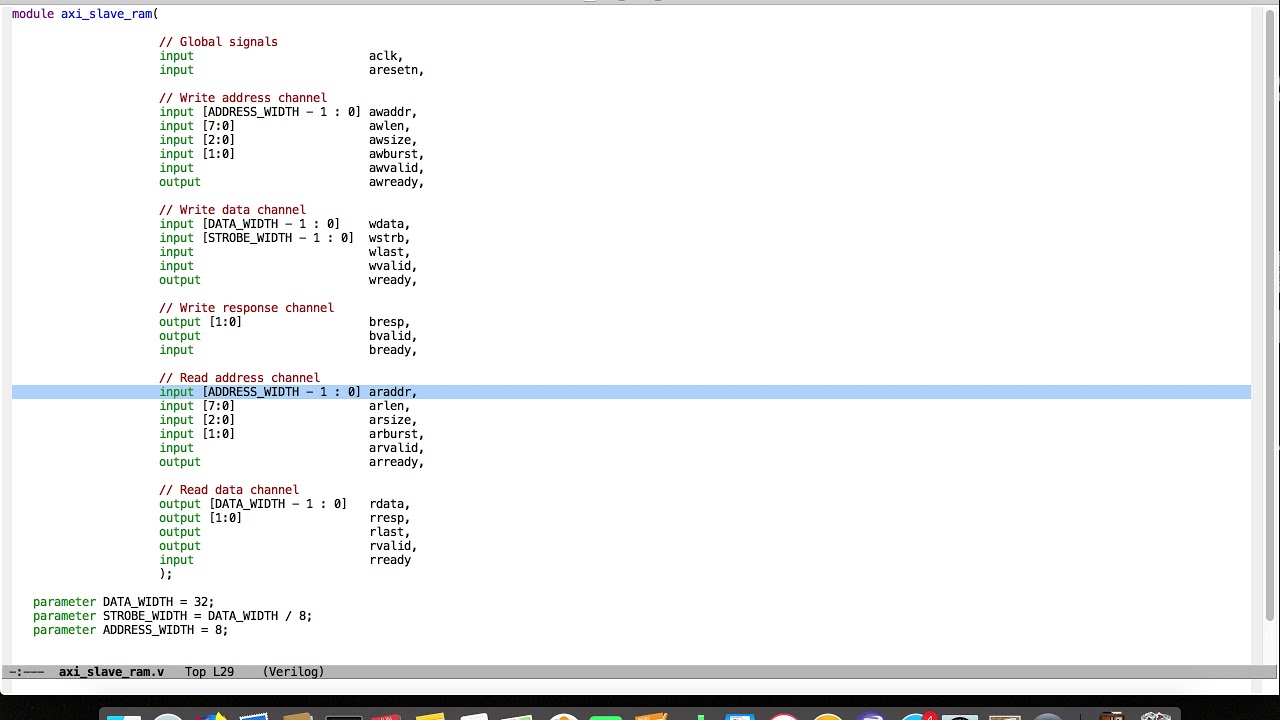
The AXI interface is parameterized to allow flexibility in address and data widths. It encapsulates all AXI channels, including write address, write data, write response, read address, and read data channels. The modport declarations specify the directionality of each signal for master and slave roles, ensuring that masters drive certain signals while slaves drive others.
2. Master Module Implementation
The master module controls the initiation of AXI transactions. In the example, the master module sets up write and read transactions by asserting the necessary signals. The always_ff block ensures that these operations are synchronized with the clock and reset signals.
3. Slave Module Implementation
The slave module responds to the master's transactions. It handles the handshake for write and read channels, provides appropriate responses, and supplies read data when requested. The slave's behavior is also managed within an always_ff block, ensuring proper synchronization.
4. Top-Level Module Configuration
The top-level module instantiates the AXI interface and connects it to both the master and slave modules via the defined modports. It also generates the necessary clock and reset signals to drive the synchronous operations of the interface and modules.
Advanced Considerations
Parameterization for Flexibility
Parameterizing the AXI interface and modules allows designers to easily adjust address and data widths without modifying the core logic. This flexibility is crucial for adapting designs to different system requirements.
Signal Synchronization and Timing
Ensuring that all signals are properly synchronized with the clock is essential for reliable operation. Proper timing management prevents issues like metastability and ensures that transactions occur as expected.
Interface Reusability
By defining a comprehensive AXI interface, the same interface can be reused across multiple modules, promoting code reuse and reducing the potential for errors in signal connections.
Error Handling and Response Management
Implementing robust error handling mechanisms, such as proper response signaling in the slave module, ensures that the system can gracefully handle exceptional conditions and maintain reliable communication.
Best Practices
-
Encapsulation: Encapsulate all related signals within an interface to promote modularity.
-
Clear Modport Definitions: Clearly define modports to specify the direction of each signal, minimizing connectivity errors.
-
Consistent Naming Conventions: Use consistent and descriptive naming conventions for signals and modules to enhance readability.
-
Parameterization: Parameterize interfaces and modules to allow flexibility and reuse across different applications.
-
Proper Synchronization: Ensure all signals are properly synchronized with the clock and reset signals to avoid timing issues.
-
Comprehensive Documentation: Document the interface and module functionalities to facilitate maintenance and collaboration.
Conclusion
Implementing AXI interfaces in SystemVerilog using interfaces and modports significantly enhances the modularity, readability, and reusability of hardware designs. By encapsulating related signals within an interface and clearly defining modports for master and slave roles, designers can create robust and scalable systems. Parameterization further adds flexibility, allowing designs to adapt to varying system requirements with minimal modifications.
References
Last updated January 26, 2025