
Transformer Principles: Turns Ratio, Power Conservation, Losses, and HVDC vs. HVAC Transmission
Exploring the fundamentals of transformers, energy losses, and a comparison of HVDC and HVAC transmission systems.
Key Highlights
- Turns Ratio Derivation: The turns ratio equation \( \frac{V_P}{V_S} = \frac{N_P}{N_S} \) stems directly from Faraday's Law, linking voltage and the number of coil turns.
- Power Conservation in Ideal Transformers: In ideal transformers, power is conserved (\( V_1 I_1 = V_2 I_2 \)), indicating lossless energy transfer between primary and secondary windings.
- HVDC vs. HVAC: HVDC excels in long-distance efficiency and environmental footprint, while HVAC is more cost-effective for shorter distances and easier for voltage step-up/step-down.
Turns Ratio Equation Derivation from Faraday's Law
The turns ratio equation, \( \frac{V_P}{V_S} = \frac{N_P}{N_S} \), can be derived from Faraday's Law of electromagnetic induction. Faraday's Law states that the induced voltage in a coil is proportional to the rate of change of magnetic flux through the coil and the number of turns in the coil. For the primary and secondary coils of a transformer, this can be expressed as:
\[ V_P = N_P \frac{d\Phi}{dt} \] \[ V_S = N_S \frac{d\Phi}{dt} \]Where:
- \( V_P \) is the voltage in the primary coil.
- \( V_S \) is the voltage in the secondary coil.
- \( N_P \) is the number of turns in the primary coil.
- \( N_S \) is the number of turns in the secondary coil.
- \( \frac{d\Phi}{dt} \) is the rate of change of magnetic flux through the coils.
Dividing the primary voltage equation by the secondary voltage equation, we get:
\[ \frac{V_P}{V_S} = \frac{N_P \frac{d\Phi}{dt}}{N_S \frac{d\Phi}{dt}} \]Since the rate of change of magnetic flux \( \frac{d\Phi}{dt} \) is the same for both coils in an ideal transformer, it cancels out, resulting in the turns ratio equation:
\[ \frac{V_P}{V_S} = \frac{N_P}{N_S} \]This equation shows that the ratio of the primary voltage to the secondary voltage is equal to the ratio of the number of turns in the primary coil to the number of turns in the secondary coil.
Power Conservation in Ideal Transformers
In an ideal transformer, power is conserved, which means the power in the primary coil (\( P_1 \)) is equal to the power in the secondary coil (\( P_2 \)). This can be expressed as \( P_1 = P_2 \). Power is calculated as the product of voltage and current, so:
\[ V_1 I_1 = V_2 I_2 \]Where:
- \( V_1 \) is the voltage in the primary coil.
- \( I_1 \) is the current in the primary coil.
- \( V_2 \) is the voltage in the secondary coil.
- \( I_2 \) is the current in the secondary coil.
This equation holds true for ideal transformers because they are assumed to have no losses. In other words, all the energy supplied to the primary coil is transferred to the secondary coil without any energy being converted to heat or other forms of energy. The transformer turns ratio plays a key role in maintaining this balance, ensuring efficient and safe power delivery.
Sources of Energy Loss in Real Transformers
Real transformers are not ideal and experience energy losses due to several factors. Here are three significant sources of energy loss:
Hysteresis Losses
Hysteresis losses occur due to the energy required to repeatedly magnetize and demagnetize the transformer core as the alternating current flows. The magnetic domains in the core material do not align perfectly with the changing magnetic field, and energy is dissipated as heat during this process. The energy wasted overcoming this "magnetic friction" appears as heat, reducing transformer efficiency.
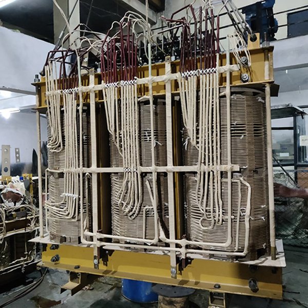
An electric core transformer.
Eddy Current Losses
Eddy current losses are caused by circulating currents induced in the transformer core by the changing magnetic field. These currents flow in closed loops within the core material, dissipating energy as heat due to the core's resistance. These circulating currents act like short circuits within the core, leading to significant energy loss.
Copper Losses (\(I^2R\) Losses)
Copper losses, also known as \(I^2R\) losses, occur due to the resistance of the transformer windings. When current flows through the windings, energy is dissipated as heat due to the resistance of the copper wire. These losses are proportional to the square of the current (\(I^2\)) and the resistance (\(R\)) of the windings. Using thicker wire reduces resistance and minimizes these losses.
Laminating the Core to Reduce Eddy Current Losses
Laminating the core is an effective method to reduce eddy current losses in transformers. The core is constructed from thin sheets of iron or steel, electrically insulated from each other. This lamination increases the resistance to eddy current flow. By dividing the core into thin, insulated layers, the path for eddy currents becomes longer and narrower, significantly increasing the resistance and reducing the magnitude of the eddy currents. This minimizes heat dissipation and improves transformer efficiency.
HVDC vs. HVAC Transmission Systems
High Voltage Direct Current (HVDC) and High Voltage Alternating Current (HVAC) transmission systems are two primary methods for transmitting electrical power over long distances. Each has its own advantages and disadvantages, making them suitable for different applications.
Efficiency Over Long Distances
HVDC transmission is generally more efficient than HVAC for long distances. This is because HVDC systems experience lower power losses due to several factors:
- No Reactive Power: HVDC lines do not require reactive power compensation, reducing voltage drops and losses.
- Skin Effect: The skin effect, which increases the effective resistance of conductors in HVAC systems, is absent in HVDC systems, allowing for more efficient use of the conductor's cross-sectional area.
- Corona Losses: HVDC transmission lines have lower corona losses compared to HVAC lines due to the constant voltage polarity.
HVDC is more environmentally friendly because it provides more energy per square meter over greater distances more efficiently than AC systems, with lower losses and less space requirements.
HVDC overhead line design considerations.
Cost and Environmental Impact
The cost comparison between HVAC and HVDC depends largely on distance. HVDC systems have higher initial costs due to the need for converter stations at each end to convert AC to DC and back. However, for long distances, the lower losses and reduced infrastructure requirements (e.g., fewer conductors, smaller towers) make HVDC more economical.
From an environmental perspective, HVDC systems generally have a lower impact:
- Land Use: HVDC lines typically require less land area compared to HVAC lines.
- Electromagnetic Interference: HVDC lines produce less electromagnetic interference with nearby communication lines.
- Visual Impact: HVDC lines can be constructed with smaller towers and spacing, reducing their visual impact.
Typical Applications
HVDC and HVAC systems are used in a variety of applications, depending on the specific requirements of the power transmission system.
- HVDC Applications:
- Long-Distance Transmission: HVDC is ideal for transmitting large amounts of power over long distances with minimal losses.
- Submarine Cables: HVDC is commonly used for undersea power transmission, such as connecting offshore wind farms to the mainland grid.
- Asynchronous Interconnections: HVDC can connect AC systems operating at different frequencies or phases, providing grid stability and reliability.
- HVAC Applications:
-
Short- to Medium-Distance Transmission: HVAC is cost-effective for shorter distances where the cost of converter stations outweighs the benefits of lower losses.
-
Distribution Networks: HVAC is widely used in distribution networks to deliver power to homes and businesses.
-
Voltage Transformation: HVAC systems allow for easy voltage step-up and step-down using transformers.
-
Here is a table summarizing the key differences between HVDC and HVAC transmission systems:
| Feature | HVDC | HVAC |
|---|---|---|
| Efficiency | Higher for long distances | Lower for long distances |
| Cost | Higher initial cost due to converters | Lower initial cost |
| Distance | Economical for long distances (600-800 km) | Economical for short distances |
| Land Use | Less land required | More land required |
| Conductors | Requires fewer conductors | Requires more conductors |
| Reactive Power | No reactive power compensation needed | Requires reactive power compensation |
| Applications | Long-distance, submarine cables, asynchronous interconnections | Short- to medium-distance, distribution networks, voltage transformation |
| Environmental Impact | Lower electromagnetic interference, smaller towers | Higher electromagnetic interference, larger towers |
FAQ
What is the primary advantage of using HVDC for long-distance power transmission?
HVDC transmission is more efficient over long distances due to lower power losses, absence of reactive power requirements, and reduced skin effect.
Why are transformer cores laminated?
Transformer cores are laminated to reduce eddy current losses by increasing the resistance to circulating currents within the core material.
What does the turns ratio of a transformer signify?
The turns ratio of a transformer indicates the voltage transformation ratio between the primary and secondary circuits, determining whether the transformer is a step-up or step-down type.
How do copper losses affect transformer efficiency?
Copper losses, or \(I^2R\) losses, reduce transformer efficiency by dissipating energy as heat due to the resistance of the transformer windings.
References
Last updated April 13, 2025