
Unlocking Peak Testability: Optimizing Verilog RTL for Superior ATPG Stuck-At Fault Coverage
Enhancing VLSI design robustness through strategic RTL modifications and Design-for-Testability (DFT) integration.
Key Insights for Enhanced ATPG Coverage
- Scan Chain Integration: The most impactful DFT technique, scan chains convert sequential logic into testable shift registers, dramatically improving controllability and observability for ATPG.
- RTL Coding Discipline: Adhering to strict, test-friendly coding guidelines—such as avoiding asynchronous logic and combinational loops—is fundamental to preventing untestable faults and simplifying ATPG.
- Early Testability Analysis: Proactive fault simulation and DFT analysis at the RTL stage enable designers to identify and resolve testability issues before synthesis, saving significant time and resources.
Optimizing Verilog Register Transfer Level (RTL) designs for superior Automatic Test Pattern Generation (ATPG) stuck-at fault coverage is paramount for ensuring the reliability and quality of integrated circuits. The stuck-at fault model, which postulates that a circuit node is permanently fixed at either a logic '0' or '1', is a cornerstone of digital circuit testing. High fault coverage signifies that manufacturing defects are effectively detectable, leading to more robust and dependable semiconductor devices.
This comprehensive guide delves into various strategies, methodologies, and best practices that can be implemented at the RTL stage to significantly enhance ATPG stuck-at fault coverage. The focus is on making internal circuit nodes fully controllable and observable by ATPG tools, thereby simplifying the test pattern generation process and improving fault detection capabilities.
The Foundation: Understanding Stuck-At Faults and ATPG
The stuck-at fault model is a widely adopted abstraction for modeling common manufacturing defects. ATPG tools are designed to create input patterns (test vectors) that, when applied to a circuit, activate these hypothetical stuck-at faults and propagate their effects to observable outputs, such as primary output pins or scan chain flip-flops. Achieving high fault coverage, often exceeding 95%, is a critical metric for production testing. The success of ATPG is directly tied to the circuit's inherent testability, which hinges on two key concepts: controllability and observability.
- Controllability: The ability to set any internal node within the circuit to a desired logic value (0 or 1) through the circuit's primary inputs or scan chains.
- Observability: The ability to propagate the logic value (or the effect of a fault) from any internal node to a primary output or a scan chain flip-flop, where it can be detected.
Optimizing Verilog RTL designs primarily involves architecting the design such that these two properties are maximized for every node.
Strategic RTL Design Practices for Enhanced ATPG Coverage
Integrating Design-for-Testability (DFT) Techniques
DFT techniques are systematic approaches embedded into the design process to enhance testability. Their early adoption at the RTL stage is crucial.
Embracing Scan Chain Insertion
Scan chain insertion is undeniably the most effective DFT technique for improving stuck-at fault coverage. It transforms sequential elements (flip-flops) into a series of shift registers during test mode. This reconfiguration allows ATPG tools to directly control and observe the state of these internal storage elements, effectively converting a complex sequential testing problem into a more manageable combinational one. Implementing full scan designs, where all flip-flops are integrated into scan chains, can lead to fault coverage rates well above 95%.
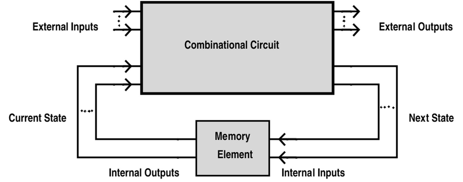
An illustration depicting the basic concept of scan chain integration in DFT.
Controlling Clocks and Resets Effectively
For ATPG tools to function reliably, all clock and reset signals must be fully controllable. Designers should avoid asynchronous resets and complex clock generation schemes within the RTL. Synchronous resets, where the reset signal is sampled on a clock edge, simplify scan insertion and fault propagation. Any clock or reset signal generated by logic within the design should have dedicated test control logic to ensure it can be independently controlled during test mode.
Avoiding Problematic RTL Constructs
Certain Verilog coding styles can inherently impede ATPG efficiency and lead to untestable faults. Designers must meticulously avoid:
- Asynchronous logic and pulse generators: These can create race conditions and unpredictable behavior, making it difficult for ATPG algorithms to deterministically test faults.
- Combinational feedback loops: These loops violate the zero-delay assumption of ATPG tools for combinational elements and can lead to oscillations or indeterminate states, rendering the affected logic untestable.
- Redundant logic or unused gates: These can mask faults or introduce untestable points. Simplifying logic expressions and removing unnecessary multiplexing can help.
initialstatements for logic initialization: In synthesizable RTL,initialblocks do not represent real hardware behavior and should be avoided for setting up logic states, as ATPG tools rely on the actual power-on state and test mode controllability.- Unintended latches: Implicit latches formed by incomplete
caseorif-elsestatements can complicate ATPG, as latches are more difficult to test than flip-flops. Explicitly defining all outputs in all conditions or using a default assignment can prevent this.
Optimizing RTL Coding Style and Structure
The clarity, modularity, and consistency of the RTL code directly impact testability. A well-structured design simplifies the task of ATPG tools and human designers alike.
Modular and Hierarchical Design
Breaking down complex designs into smaller, manageable, and reusable modules enhances testability by allowing for hierarchical ATPG and fault simulation. This approach isolates faults within specific modules, simplifying debugging and test pattern generation for individual blocks before integrating them into the larger system.

Visualizing hierarchical design in Verilog, where complex systems are built from reusable blocks.
Parameterization and Generics
Using parameters in Verilog allows for configurable and flexible designs. This can simplify test pattern generation for different configurations of a module, as the underlying test methodology can be applied to various instantiations without significant modification.
Test-Specific Control Signals and Test Points
For areas identified with low fault coverage, adding explicit test points or control signals can provide ATPG tools with direct access to otherwise hard-to-reach nodes. These can be simple muxes or dedicated input/output pins activated only in test mode, improving controllability or observability of critical internal signals without affecting functional operation.
Clock Gating Awareness
While clock gating is essential for power optimization, it can inadvertently reduce test coverage if not handled carefully. During test mode, clock gating logic should be disabled or bypassed to ensure that all registers receive clock signals and can toggle, allowing faults to propagate correctly.
Early Analysis and Verification for Proactive Testability
Shifting testability analysis earlier into the design flow, specifically at the RTL stage, is a highly effective strategy for preventing costly redesigns post-synthesis.
This radar chart illustrates the perceived impact on ATPG coverage and the effort level required for implementing various optimization techniques at the RTL stage. "Scan Chain Integration" shows a very high impact on coverage, reflecting its effectiveness, but also a significant effort due to its pervasive nature. "Avoiding Bad Constructs" has a substantial impact with moderate effort, emphasizing the importance of disciplined coding. "Early Fault Analysis" and "Advanced Tool Leverage" also score high on impact, highlighting the benefits of proactive and automated approaches.
RTL-Level Fault Simulation and DFT Analysis
Tools capable of performing fault simulation directly on the RTL design allow designers to identify low-coverage areas or untestable faults much earlier in the design cycle. This proactive analysis enables iterative optimization of the Verilog code, for instance, by adding test points, modifying logic, or refining the DFT strategy. Such early analysis helps to identify the minimum test vectors required for high fault coverage, thereby reducing test time and improving efficiency.
ATPG-Aware RTL Design Flow
Adopting an ATPG-aware design flow means that testability is a consideration from the very beginning of the RTL coding phase. This involves structuring the RTL in a way that inherently facilitates ATPG tool operations. For complex designs, hierarchical DFT flows can be employed, where the design is partitioned into testable blocks, and ATPG is applied at different levels of hierarchy. This approach can significantly improve stuck-at coverage by allowing focused testing of subsystems.
Leveraging Modern Tools and Automation
The semiconductor industry relies heavily on sophisticated Electronic Design Automation (EDA) tools to manage the complexity of VLSI design. These tools are indispensable for optimizing Verilog RTL for testability.
Integrated ATPG and Synthesis Tools
Modern synthesis tools are often ATPG-aware, meaning they can optimize the RTL netlist for testability during the synthesis process. They can perform checks for design rules related to testability, verify the integrity of scan chains, and even insert necessary test logic. Tools like Siemens Tessent offer comprehensive RTL-level DFT and ATPG solutions that streamline the process and ensure high fault coverage.
An "EXPERT's TALK" video on Design for Testability (DFT), which covers crucial topics like MBIST, ATPG, and JTAG. This video provides a high-level overview of the DFT landscape and its relevance in modern VLSI design, emphasizing how these techniques contribute to making designs testable and robust.
Automated Test Coverage Analysis and Reporting
Automated tools provide detailed fault coverage reports, highlighting untested faults and the reasons for their untestability. This enables designers to quickly identify "holes" in test coverage and iterate on their RTL design or DFT strategy. Analyzing untestable faults may lead to design modifications, such as adding bypass multiplexers or test wrappers around hard-to-test blocks.
A Holistic View of RTL Optimization for ATPG Coverage
To summarize, optimizing Verilog RTL designs for better ATPG stuck-at fault coverage involves a multi-faceted approach encompassing disciplined coding, strategic DFT insertion, early analysis, and intelligent tool usage. The following table provides a concise overview of key optimization aspects and their impact.
| Aspect | Optimization Technique | Impact on ATPG Stuck-At Coverage | Key Benefit |
|---|---|---|---|
| Structural Testability | Scan Chain Insertion (Full/Partial Scan) | Significantly improves controllability and observability. | Converts sequential testing to combinational. |
| Logic Simplification | Reduce complex/redundant logic, avoid combinational loops. | Enhances fault activation and propagation. | Prevents untestable faults and simplifies ATPG. |
| Synchronicity & Control | Use synchronous resets, fully controllable clocks/resets. | Simplifies ATPG pattern generation and scan operations. | Ensures predictable logic behavior during test. |
| RTL Coding Style | Modular design, use parameters, avoid problematic constructs. | Improves ATPG tool efficiency and reduces errors. | Enhances code clarity, reusability, and testability. |
| Early Analysis | RTL-level fault simulation, DFT analysis, ATPG-aware design. | Identifies testability issues proactively. | Reduces costly post-synthesis redesigns. |
| Test Point Insertion | Manually or automatically add test points. | Improves controllability/observability of hard-to-test nodes. | Targets specific coverage holes. |
| Automation & Tools | Leverage ATPG-aware synthesis, hierarchical ATPG, ML/AI methods. | Automates optimization, improves efficiency, finds complex faults. | Maximizes coverage with less manual effort. |
The successful implementation of these strategies relies on a deep understanding of how Verilog RTL code translates into physical hardware and how ATPG tools interact with the resulting netlist. Continuous iteration between RTL design, DFT insertion, and fault simulation is crucial for achieving high fault coverage and ensuring product reliability.
Mindmap of RTL Optimization Strategies
This mindmap visually organizes the key strategies and considerations for optimizing Verilog RTL designs to achieve better ATPG stuck-at fault coverage. It branches out from the central theme to fundamental concepts, specific DFT techniques, recommended RTL coding practices, the importance of early analysis, and the role of automation and tools. Each node represents a distinct area of focus, illustrating their interconnectedness in a holistic optimization strategy.
Frequently Asked Questions (FAQ)
What is a stuck-at fault?
Why is high ATPG stuck-at fault coverage important?
How do scan chains improve fault coverage?
Can asynchronous logic hurt ATPG stuck-at coverage?
What is "ATPG-aware RTL design"?
Conclusion
Optimizing Verilog RTL designs for enhanced ATPG stuck-at fault coverage is a critical, multi-layered process that demands meticulous attention throughout the design flow. It is not merely a post-design verification step but an integral part of the RTL development itself. By diligently applying Design-for-Testability (DFT) techniques, adhering to rigorous coding standards, leveraging advanced EDA tools for early analysis and automation, and continuously iterating based on fault coverage feedback, designers can significantly improve the testability of their integrated circuits. The ultimate goal is to produce robust, reliable semiconductor devices that effectively detect manufacturing defects, thereby ensuring product quality and reducing testing costs. Proactive testability considerations at the RTL stage lay the foundation for a successful and efficient silicon realization.
Recommended Further Exploration
- Advanced Design for Testability techniques for VLSI
- Hierarchical ATPG and fault simulation methods
- Impact of clock gating on testability in RTL
- Machine learning applications in RTL design for testability
Referenced Search Results
 vlsi-doubts.blogspot.com