
Unlocking Bluetooth Low Energy: A Deep Dive into its RF Heartbeat and Data Language
Discover the intricacies of BLE's efficient wireless communication, from radio signals to packet structures.
Highlights
- Ultra-Low Power: BLE is designed for minimal energy consumption, enabling long battery life for connected devices by using short data bursts and sleep modes.
- Robust RF Communication: Operating in the 2.4 GHz ISM band, BLE employs frequency hopping across 40 channels to mitigate interference and ensure reliable data transfer.
- Structured Data Exchange: BLE uses specific packet formats for advertising and data transmission, managed by distinct layers in its protocol stack for efficient and organized communication.
Introduction to Bluetooth Low Energy (BLE)
Bluetooth Low Energy (BLE), introduced as part of the Bluetooth 4.0 specification in 2010 and continually evolving, is a wireless communication technology tailored for short-range applications demanding minimal power consumption. It's distinct from Bluetooth Classic, though it shares the same 2.4 GHz frequency band. BLE excels in scenarios involving the Internet of Things (IoT), wearables, health monitors, beacons, and other battery-powered devices where transmitting small amounts of data periodically is sufficient. Its core design philosophy revolves around energy efficiency, achieved through optimized protocols, brief communication windows, and extensive use of sleep modes.
The BLE Radio Frequency (RF) Protocol Explained
The foundation of BLE communication lies in its RF protocol, which dictates how devices transmit and receive signals wirelessly. Understanding this layer is crucial to appreciating BLE's efficiency and reliability.
Operating Frequency and Channelization
BLE operates within the globally unlicensed 2.4 GHz Industrial, Scientific, and Medical (ISM) band, specifically from 2402 MHz to 2480 MHz. This spectrum is divided into 40 RF channels, each 2 MHz wide.
- Advertising Channels (3): Channels 37 (2402 MHz), 38 (2426 MHz), and 39 (2480 MHz) are exclusively used for device discovery (advertising), broadcasting data, and initiating connections. Placing these channels strategically between common Wi-Fi channels helps reduce interference during the critical discovery phase.
- Data Channels (37): Channels 0 through 36 are used for bidirectional data communication once a connection is established between two devices.
Modulation and Physical Layer (PHY)
BLE employs Gaussian Frequency-Shift Keying (GFSK) modulation for transmitting data over the air. This modulation scheme is chosen for its balance between spectral efficiency and power efficiency.
The Physical Layer (PHY) is responsible for the actual RF signal transmission and reception. BLE supports several PHY variants, offering trade-offs between data rate, range, and power consumption:
- LE 1M PHY: The original mandatory PHY, offering a symbol rate of 1 Megasymbol per second (Msym/s), translating to a raw data rate of 1 Mbps.
- LE 2M PHY (Bluetooth 5.0+): Offers a 2 Msym/s rate, doubling the raw data rate to 2 Mbps, suitable for faster data transfer at a slightly reduced range compared to 1M.
- LE Coded PHY (Bluetooth 5.0+): Uses Forward Error Correction (FEC) coding (S=2 or S=8) to significantly increase communication range (up to 4x compared to 1M PHY) at the cost of data rate (reducing it to 500 kbps or 125 kbps). This is ideal for applications requiring longer reach, like asset tracking or smart home devices spread across a larger area.
Frequency Hopping Spread Spectrum (FHSS)
To combat interference prevalent in the crowded 2.4 GHz band (from Wi-Fi, microwaves, classic Bluetooth, etc.), BLE utilizes Adaptive Frequency Hopping (AFH). Once two devices establish a connection, they agree on a pseudo-random hopping sequence across the 37 available data channels. They jump from one channel to another between transmissions (connection events). AFH allows devices to identify and avoid using "bad" channels that are experiencing high interference, enhancing communication robustness.
Link Layer Roles and States
The Link Layer sits above the PHY and manages the RF state, packet formatting, and communication procedures. A BLE device operates in one of several roles and states:
- Roles: Advertiser, Scanner, Master, Slave. An Advertiser broadcasts packets, a Scanner listens for them. Once a connection is formed, the initiating device (usually the Scanner) becomes the Master, and the responding device (the Advertiser) becomes the Slave.
- States: Standby, Advertising, Scanning, Initiating, Connection. Devices transition between these states based on their actions (e.g., starting advertising, scanning for devices, establishing a connection).
The Link Layer controls connection parameters like connection interval (how often devices communicate), slave latency (allowed number of skipped connection events for the slave), and supervision timeout (maximum time between valid packets before connection loss is assumed). These parameters are key to BLE's power-saving capabilities.
Dissecting BLE Data Packets
All communication in BLE occurs via packets. The structure of these packets is meticulously defined to ensure efficient and reliable data transfer over the air.
General Packet Format
Every BLE Link Layer packet, regardless of whether it's on an advertising or data channel, shares a common basic structure:
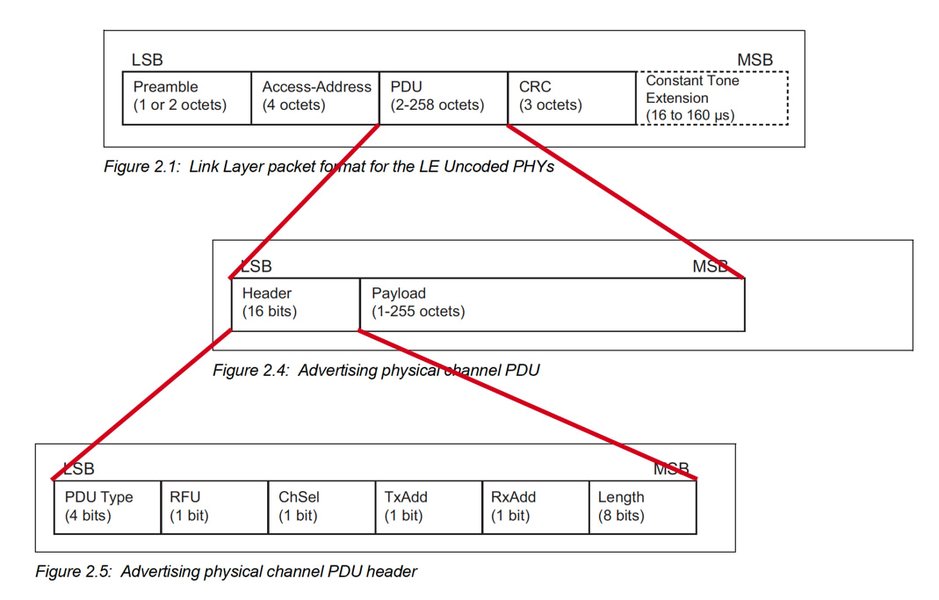
General structure of a BLE packet using the Uncoded PHY.
- Preamble (1 byte): A sequence of alternating bits (01010101b or 10101010b depending on the LSB of the Access Address) used by the receiver's radio to synchronize timing and frequency with the incoming transmission.
- Access Address (4 bytes): A unique identifier for the communication link.
- For advertising channel packets, this is a fixed value: 0x8E89BED6. All devices listening for advertisements recognize this address.
- For data channel packets (within a connection), this is a unique, randomly generated 32-bit value assigned when the connection is established. It helps differentiate packets belonging to a specific connection from others.
- Protocol Data Unit (PDU) (2 to 257 bytes): This contains the actual control information and/or payload data. Its internal structure varies depending on whether it's an advertising or data channel packet.
- Cyclic Redundancy Check (CRC) (3 bytes): A 24-bit checksum calculated over the PDU. The receiver performs the same calculation; if the calculated CRC matches the received CRC, the packet is considered valid and error-free. If not, the packet is typically discarded.
Advertising Channel PDU
Used for broadcasting information and establishing connections. The PDU structure for advertising packets is as follows:
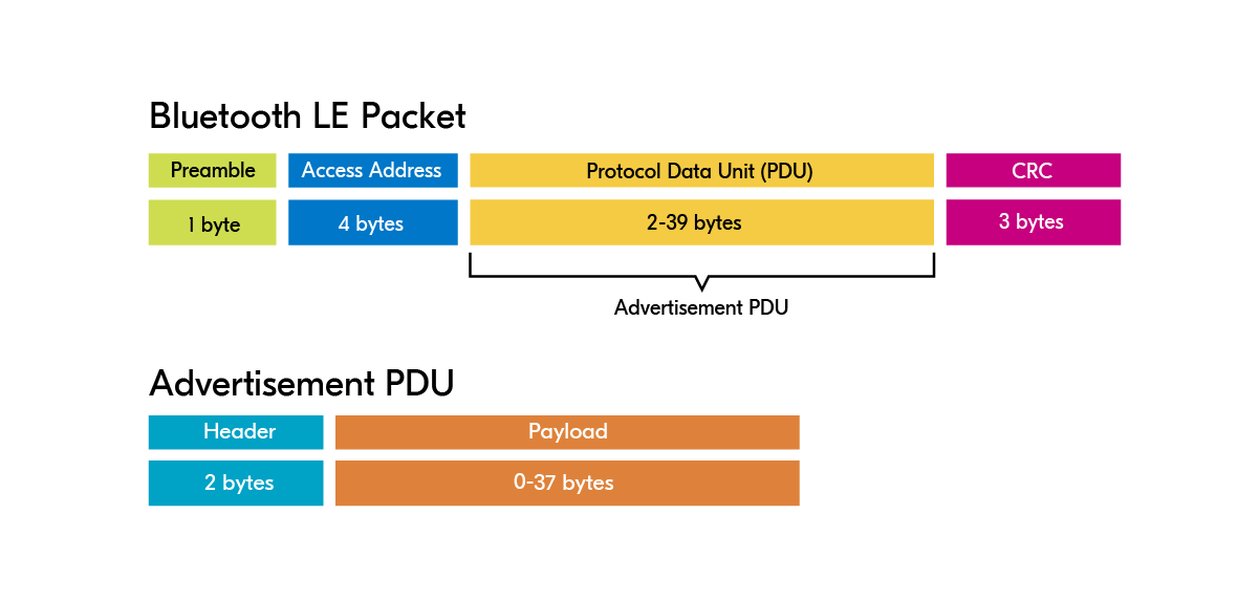
Structure of a BLE Advertising Channel PDU.
- Header (2 bytes): Contains information about the PDU type (e.g., ADV_IND for connectable undirected advertising, SCAN_REQ for scan request), device address type (public or random), and the PDU length (excluding the header itself).
- Payload (0 to 37 bytes for legacy advertising): Contains the advertiser's address (6 bytes) and the actual advertising data.
- Advertising Data (AdvData) / Scan Response Data (ScanRspData): Up to 31 bytes available for payload data in legacy advertising (prior to Bluetooth 5 extensions). This data is formatted as a sequence of AD (Advertisement Data) structures. Each AD structure consists of:
- Length (1 byte): Specifies the length of the following Type and Data fields.
- Type (1 byte): Defines the kind of data being presented (e.g., device name, service UUIDs, manufacturer-specific data).
- Data (Variable length): The actual data corresponding to the Type.
- Advertising Data (AdvData) / Scan Response Data (ScanRspData): Up to 31 bytes available for payload data in legacy advertising (prior to Bluetooth 5 extensions). This data is formatted as a sequence of AD (Advertisement Data) structures. Each AD structure consists of:
Bluetooth 5 introduced Extended Advertising, allowing much larger payloads (up to 254 bytes per data fragment) and the ability to chain fragments together, enabling more complex advertising data to be broadcast, potentially offloaded from advertising channels to data channels.
Data Channel PDU
Used for bidirectional communication within an established connection. The PDU structure is:
- Header (2 bytes): Contains control flags and length information:
- LLID (Link Layer ID): Indicates if the packet is a data fragment (continuation or start) or a Link Layer control PDU.
- NESN (Next Expected Sequence Number): Used for acknowledgement.
- SN (Sequence Number): Used to detect duplicate packets.
- MD (More Data): Indicates if the sender has more data to send in the current connection event.
- Length: Specifies the length of the Payload and MIC (if present).
- Payload (0 to 251 bytes): Carries the actual application data (typically L2CAP packets, which in turn carry ATT/GATT data) or Link Layer control messages. The maximum payload size was initially 27 bytes but was increased to 251 bytes with the introduction of the Data Packet Length Extension (DLE) feature in Bluetooth 4.2.
- Message Integrity Check (MIC) (4 bytes, Optional): Present only if the connection is encrypted. It ensures data authenticity and integrity, preventing tampering.
Packet Field Summary Table
This table summarizes the core components found across BLE packets:
| Field | Size (Bytes) | Channel Type | Description |
|---|---|---|---|
| Preamble | 1 | Advertising & Data | Synchronization pattern for receiver timing/frequency lock. |
| Access Address | 4 | Advertising & Data | Identifies the link. Fixed for Advertising (0x8E89BED6), unique per connection for Data. |
| PDU Header | 2 | Advertising & Data | Contains PDU type, flags, and length information. Structure differs slightly between Advertising and Data channels. |
| PDU Payload | 0-37 (Legacy Adv) 0-251 (Data w/ DLE) |
Advertising & Data | Carries Advertiser Address + AD structures (Advertising) or L2CAP/application data (Data). Size depends on packet type and features like DLE. |
| CRC | 3 | Advertising & Data | 24-bit Cyclic Redundancy Check for error detection across the PDU. |
| MIC | 4 (Optional) | Data | Message Integrity Check, present only in encrypted Data channel packets for authentication. |
BLE Communication Flow
Understanding the packet structure helps visualize how BLE devices communicate:
- Advertising: A peripheral device enters the Advertising state, periodically sending Advertising Channel Packets (e.g., ADV_IND) on the three advertising channels. These packets contain the device's address and potentially some data (like its name or services offered).
- Scanning & Connection Initiation: A central device enters the Scanning state, listening on advertising channels. When it receives an advertisement from a desired peripheral, it can transition to the Initiating state and send a CONNECT_REQ (or CONNECT_IND) packet back to the peripheral on the same advertising channel. This packet contains essential parameters for the connection (like the unique Access Address, connection interval, channel map, hop increment).
- Connection: If the peripheral accepts the connection request, both devices switch to the Connection state. They stop using advertising channels and start communicating exclusively on data channels using the agreed-upon parameters (Access Address, timing, frequency hopping sequence).
- Data Exchange: Within the connection, devices exchange Data Channel Packets during periodic "connection events." The master transmits first, followed by the slave (if it has data). They hop to a new data channel for the next connection event according to the FHSS algorithm. Data is typically exchanged using the ATT/GATT protocols encapsulated within L2CAP packets, which form the payload of the Link Layer data packets.
- Power Saving: Between connection events, both devices can enter low-power sleep modes, waking up just in time for the next scheduled transmission/reception, drastically reducing overall energy consumption. Slave Latency allows the slave device to skip a certain number of connection events if it has no data to send, further saving power.
BLE Protocol Stack Context
The RF protocol and packet structures operate within the lower layers of the comprehensive BLE protocol stack. This layered architecture allows for modularity and standardized communication.
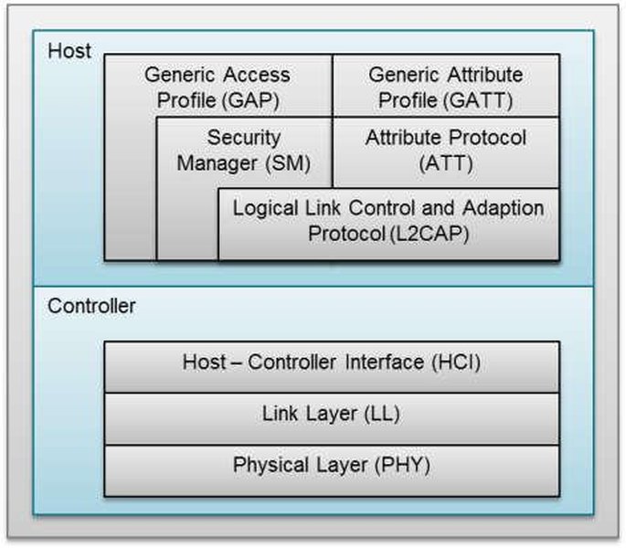
A typical representation of the BLE Protocol Stack layers.
Controller Layers
- Physical Layer (PHY): Manages RF transmission and reception (GFSK modulation, channels).
- Link Layer (LL): Handles packet formatting, advertising, scanning, connection management, FHSS, CRC, acknowledgements, and flow control.
Host Layers
- Host Controller Interface (HCI): A standardized interface allowing the Host (e.g., application CPU) to communicate with the Controller (e.g., radio chip).
- Logical Link Control and Adaptation Protocol (L2CAP): Multiplexes data from upper layers, handles fragmentation and reassembly of larger packets.
- Security Manager Protocol (SMP): Manages pairing, authentication, and encryption key distribution.
- Attribute Protocol (ATT): Defines a simple client-server protocol for discovering, reading, and writing data "attributes" on a peer device.
- Generic Attribute Profile (GATT): Defines the structure and format of data using ATT. It organizes data into Services and Characteristics (e.g., a "Heart Rate Service" containing a "Heart Rate Measurement" Characteristic).
Application Layer
- Generic Access Profile (GAP): Defines device roles (Central, Peripheral), advertising procedures, connection establishment, and security modes.
- Application Profile/Service: Defines the specific use case and how GATT Services and Characteristics are used to achieve it (e.g., Heart Rate Profile, Proximity Profile). Custom applications and services reside here.
Data packets generated by the application flow down through GATT, ATT, L2CAP, and HCI to the Link Layer, which formats them into the BLE packets described earlier for transmission by the PHY.
Visualizing BLE Concepts
BLE Technology Mindmap
This mindmap provides a visual summary connecting the core aspects of BLE's RF protocol and packet structure discussed above.
BLE PHY Comparison
The choice of BLE PHY significantly impacts performance characteristics. This radar chart provides an opinionated comparison of the three main PHY options based on key factors (higher values generally indicate better performance in that category, except for Power Consumption where lower is better, hence it's inverted as 'Power Efficiency'). Note that these are relative comparisons for illustrative purposes.
Video Explainer: BLE Fundamentals
For a visual and auditory explanation of the core concepts behind Bluetooth Low Energy, including its architecture and basic operation principles discussed here, watch the following video:
Master BLE Basics in Just 10 Minutes: The Ultimate Guide! - Provides a concise overview of BLE basics.
Frequently Asked Questions (FAQ)
What is the actual data throughput of BLE?
While the raw PHY data rate can be 1 Mbps (LE 1M) or 2 Mbps (LE 2M), the actual application data throughput is significantly lower due to protocol overhead (headers, CRC, MIC), timing constraints (connection intervals, inter-frame spacing), and potential retransmissions. Practical throughput often ranges from a few kbps to several hundred kbps, depending heavily on connection parameters, PHY used, direction of data flow, packet size (DLE usage), and RF environment. For LE 1M, throughput around ~270 kbps is sometimes cited as a practical maximum, while LE 2M can push this higher, potentially towards ~1.4 Mbps under optimal conditions, though often lower in real-world scenarios.
How does BLE avoid interfering with Wi-Fi?
BLE uses several techniques to coexist with Wi-Fi and other 2.4 GHz technologies:
- Frequency Hopping (AFH): BLE connections rapidly hop between many different channels (up to 37), reducing the probability of consistently colliding with a fixed-channel Wi-Fi signal. Adaptive hopping allows BLE devices to learn and avoid channels that are actively used by Wi-Fi.
- Short Duty Cycle: BLE transmissions are typically very short and infrequent, minimizing the time they occupy any given channel.
- Channel Placement: The three advertising channels are specifically placed in parts of the band less likely to overlap directly with the primary Wi-Fi channels (1, 6, 11 in North America).
While interference can still occur in very crowded environments, these mechanisms significantly improve coexistence.
What is the difference between Advertising Data and Scan Response Data?
In legacy advertising, a peripheral device can broadcast an initial "Advertising Packet" (containing up to 31 bytes of Advertising Data). This is sent proactively and periodically.
If a scanning device (central) detects this advertisement and wants more information *before* connecting, it can send a "Scan Request" packet back to the peripheral. The peripheral can then reply with a "Scan Response" packet, which can contain an *additional* 31 bytes of Scan Response Data.
This allows peripherals to advertise basic info constantly (e.g., name) and provide more details (e.g., full list of services) only when explicitly requested by an active scanner, saving airtime and power. Not all advertising types allow for Scan Responses (e.g., non-connectable advertising).
Is the Access Address encrypted?
No, the Access Address itself is not encrypted. It is transmitted in the clear as part of the packet header. For advertising packets, it's a fixed, publicly known value. For data packets within a connection, it's a unique but unencrypted identifier for that specific link. While the Access Address helps identify the connection, security relies on encrypting the PDU payload using keys established during the pairing process (managed by the Security Manager Protocol).
Recommended
- How does BLE security work, including pairing and encryption?
- Compare BLE 5 features like Coded PHY and 2M PHY in detail.
- Explain the difference between GATT Client and GATT Server roles in BLE.
- What are BLE Beacons and how do they use advertising packets?
References
 amazon.com
Last updated May 6, 2025