
Designing a Flying Robot that Flaps Like a Bird
Exploring biomimicry, mechanics, and control for agile flight
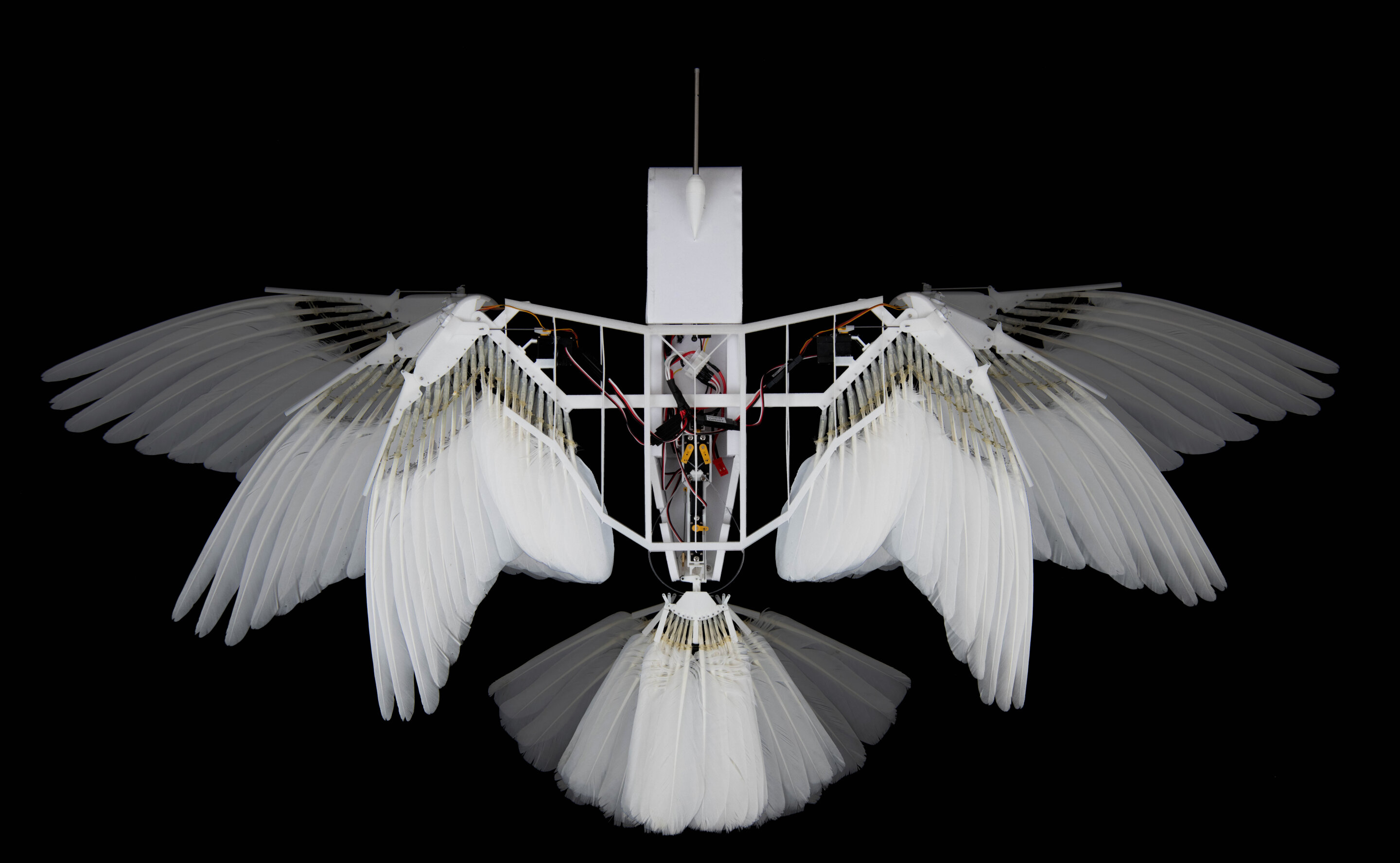
Highlights
- Biomimetic Inspiration: Emulating natural wing morphology and flapping dynamics.
- Integrated Mechanical Design: Combining lightweight materials with efficient actuation mechanisms.
- Advanced Control & Aerodynamics: Utilizing feedback systems and simulation for stable flight.
Introduction
Designing a flying robot that flaps like a bird merges the disciplines of aerodynamics, materials science, control systems, and mechanical engineering. This project draws direct inspiration from nature, specifically the mechanics observed in bird flight. By carefully studying the structure and behavior of birds, engineers develop prototypes that mirror the intricacies of natural flight, such as wing morphology, flapping mechanisms, and efficient aerodynamics.
At the core of this endeavor lies the principle of biomimicry—the imitation of natural systems to solve engineering challenges. Bird flight is a marvel of evolution, balancing strength, flexibility, and precision. Approaching the design of a flapping-wing robot by replicating these qualities opens new vistas in robotics, opening the door to advanced aerial maneuvers, energy efficiency, and adaptable flight patterns that conventional drones often fail to achieve.
Key Components for Design
1. Biomimetic and Aerodynamic Inspiration
Understanding Natural Flight
The first step in designing an ornithopter—a robot that mimics bird flight—is understanding the principles of natural flight. Birds utilize asymmetrical wing shapes, flexible joints, and muscle coordination to generate lift and thrust. Their wings have a curved upper surface and a relatively flatter underside, creating a pressure differential that enables lift. Designers replicate these features using modern materials and creative engineering.
Researchers typically study different bird species to assess wing dimensions, movements, and overall flight dynamics. Such studies can provide insights into:
- The curvature and tapering of the wings for optimal airflow management.
- The flapping frequency and amplitude that maximize lift while minimizing energy consumption.
- The flexible and adaptive behavior of real wings that adjust to changing flight conditions.
These qualitative characteristics are later translated into quantitative design parameters in simulation models and experimental prototypes.
Aerodynamic Equations and Considerations
Precise calculation and simulation are vital for achieving the balance between lift and drag. Engineers use formulas such as:
\( \text{\( L = 0.5 \rho v_{flap}^{2} S_{w} C_{l} \)} \) and \( \text{\( D = 0.5 \rho V^{2} S_{b} C_{d} \)} \), where:
- \( \text{\( \rho \)} \): Air density
- \( \text{\( v_{flap} \)} \): Wing flap velocity
- \( \text{\( S_{w} \)} \) and \( \text{\( S_{b} \)} \): Wing and body surface areas
- \( \text{\( C_{l} \)} \) and \( \text{\( C_{d} \)} \): Coefficients of lift and drag
- \( \text{\( V \)} \): Flight velocity
These equations help in simulating how variations in wing design or flapping frequency affect flight stability and efficiency.
Mechanical and Structural Design
2. Structural Mechanics and Material Selection
Wing Design
The wing design is paramount in replicating the flight of a bird. Ideal wing designs blend rigidity with flexibility. For this purpose, engineers opt for lightweight yet resilient materials such as carbon fiber composites, 3D-printed polymers, and specialized plastics.
The design process involves ensuring:
- Curvature and Flexibility: If the wing is too rigid, the aerodynamic efficiency is compromised. Conversely, excessive flexibility may result in fluttering and loss of control.
- Weight Minimization: Using advanced materials like carbon fiber ensures that the overall mass of the robot is kept minimal, critical for achieving and sustaining flight.
- Wing Thickness and Surface Area: Balancing the wing thickness and surface area ensures optimal lift generation while maintaining structural integrity.
Flapping Mechanism and Linkages
A robust flapping mechanism is essential to replicate the motion of bird wings. Successful designs often incorporate a four-bar linkage mechanism or a slider-crank setup, translating rotational motion from an engine or motor into an oscillating wing movement.
In prototypes, designers have experimented with:
- Four-Bar Linkages: These mechanisms ensure synchronized motion between the left and right wings, balancing the forces and allowing a smooth transition between upstroke and downstroke.
- Slider-Crank Mechanisms: This system converts circular motion into a reciprocating motion, which can effectively simulate the natural flapping of a bird’s wings.
- Actuation: Actuators like brushless DC motors or servo motors are integrated. Lightweight and energy-efficient motors provide robust control over wing dynamics.
The interplay between the mechanical design and the aerodynamics of the wings is tightly coupled. An optimal design minimizes energy losses while ensuring that each flap leads to sufficient lift generation.
Control Systems and Sensor Integration
3. Advanced Control and Navigation
Feedback and Autonomy
For a flapping-wing robot to outperform in dynamic environments, an advanced control system is indispensable. This system maintains the balance between lift, thrust, and drag, adapting to fluctuations in wind and other environmental factors.
To achieve reliable control:
- Sensors: Integration of accelerometers, gyroscopes, and potentially visual or ultrasonic sensors provides real-time feedback on the robot's attitude, position, and velocity.
- Closed-Loop Feedback Systems: These systems constantly adjust the wing angles and flapping frequency, ensuring the robot maintains stable flight even in turbulent conditions.
- Autonomous Navigation: Implementing algorithms for autonomous control allows the robot to evaluate its flight path dynamically, making corrections on-the-fly.
Dynamical models, sometimes using mathematical representation such as quaternions for three-dimensional orientation, further enhance the stability of the control system by anticipating how changes in wing movement affect the flight dynamics.
Control Code Example
The following is a simplified example of an Arduino program that could be used to control basic wing movement. Note that this code is a starting point and would need to be adapted for sophisticated flight control.
// Include servo library for wing control
#include <Servo.h>  // Servo library inclusion

// Define servo objects for each wing
Servo leftWing;
Servo rightWing;

void setup() {
  // Attaching servo objects to pins
  leftWing.attach(9);
  rightWing.attach(10);
}

void loop() {
  // This loop cycles wing flaps
  for (int i = 0; i < 10; i++) {
    // Wing up position (flapping up)
    leftWing.write(180);
    rightWing.write(180);
    delay(500);

    // Wing down position (flapping down)
    leftWing.write(0);
    rightWing.write(0);
    delay(500);
  }
  // Reset wings to central position for glide
  leftWing.write(90);
  rightWing.write(90);
  delay(1000);
}
This code blocks out a simple oscillation pattern for the wings, a concept that can be further developed by integrating sensor-based adjustments and refined flapping profiles.
Prototyping, Simulation, and Testing
4. Experimental Validation and Refinement
Simulation and Computational Modeling
Before building a full-scale prototype, designers use simulation tools such as MATLAB, Simulink, or dedicated aerodynamic modeling software to study the robot’s behavior in a virtual environment. These simulations help in:
- Predicting the overall flight dynamics based on the chosen wing design and flapping motion.
- Adjusting design parameters such as flap amplitude and frequency to optimize lift generation.
- Evaluating the impact of environmental conditions like wind disturbances.
Computational models, sometimes incorporating finite element analysis (FEA), allow the design team to tweak material properties and mechanical linkages before any physical fabrication begins.
Prototyping and Field Testing
After refining the design through simulation, the next step is to build a prototype. This phase involves:
- Fabrication: Using advanced manufacturing techniques such as 3D printing, CNC machining, and composite layup to construct the robot’s frame and wings.
- Ground Testing: Initiating tests from controlled environments, starting with ground-based experiments to assess the flapping mechanism and sensor responses.
- Flight Trials: Conducting flight demonstrations in controlled settings and gradually advancing to more challenging flight conditions. Early tests focus on verifying lift, stability, and maneuverability.
- Iterative Improvements: Collecting data during testing sessions allows for iterative refinement of the mechanical structure, wing kinematics, and control algorithms.
Each iteration in the prototyping cycle provides invaluable insights that help improve energy efficiency, flight duration, and responsive control.
Integration of Systems and Future Directions
5. Beyond the Basics
Material Advancements and Future Technologies
Future improvements in the design of flapping-wing robots may include the incorporation of smarter materials—such as shape-memory alloys and adaptive polymers—that change stiffness or shape in response to environmental stimuli. Such advancements can further align the mechanical behavior of a robot with the dynamic properties seen in living birds.
Nanotechnology and advancements in lightweight energy storage systems could also contribute to enhancing the performance of flying robots. Innovations in battery technology and energy management can extend flight times, enabling these robots to undertake longer missions in aerial applications like surveillance, environmental monitoring, and wildlife research.
Future Control Algorithms and Machine Learning
The integration of machine learning can allow autonomous systems to learn and adjust their flight patterns from real-time data. By incorporating adaptive control frameworks, the robot can optimize wing kinematics to dynamically respond to unpredictable flight conditions. This evolution in control strategy would involve reinforcing learning models that analyze sensor feedback and automatically adjust control inputs to maintain stability and agility.
Advancements in computational power and miniaturized processors also support more complex navigation algorithms that could enable fully autonomous flight. These new control models build upon traditional aerodynamic theories yet add layers of intelligent decision-making that can help the robot navigate varied environments.
Design Specification Table
| Component | Description | Key Considerations |
|---|---|---|
| Wing Design | Curved wing morphology inspired by birds | Lightweight materials, aerodynamic curvature, balance between rigidity and flexibility |
| Flapping Mechanism | Four-bar linkage or slider-crank mechanism converting motor motion into flapping | Synchronized movement, efficient actuation, use of brushless DC or servo motors |
| Control Systems | Feedback-driven control utilizing sensors like accelerometers and gyroscopes | Closed-loop algorithms, adaptive control, and autonomous navigation features |
| Aerodynamic Simulation | Use of mathematical models and simulation software | Lift and drag calculations, optimization of wing shape and motion frequency |
| Materials & Structure | Carbon fiber, composites, and 3D-printed elements | Durability, lightness, flexibility, and resilience under dynamic loads |
References
- Biomimicry in Robot Design - Northrop Grumman
- Bio-Inspired Aerospace Innovations - EDI Weekly
- Drones with Flapping Wings - IoT World Today
-
Flapper Drones
- Design and Analysis of Flapping Wing Robots - MDPI
Recommended Queries
Last updated March 15, 2025