
Design and Manufacture of a Laboratory Device to Calculate the Balance of Forces
A Comprehensive Guide to Developing an Accurate and Reliable Force Balance System
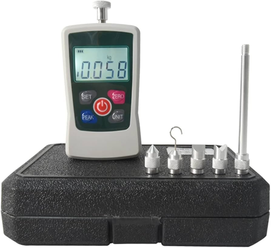
Key Takeaways
- Comprehensive Planning: Define clear objectives, specifications, and user requirements to ensure the device meets its intended purpose.
- Precision Engineering: Utilize high-quality materials and advanced sensor technologies to achieve accurate and reliable force measurements.
- Robust Calibration and Testing: Implement thorough calibration procedures and rigorous testing protocols to maintain device accuracy and longevity.
1. Introduction
Understanding Force Balance in Laboratory Settings
In laboratory environments, accurately measuring and calculating the balance of forces is essential for a wide range of applications, including research, education, and industrial testing. A force balance device provides quantitative measurements of forces acting on a system, enabling precise analysis and experimentation. This guide outlines the comprehensive process of designing and manufacturing a laboratory device tailored to calculate the balance of forces, ensuring it meets the highest standards of accuracy, reliability, and usability.
2. Defining Purpose and Specifications
Establishing Clear Objectives
a. Determine the Primary Use
The first step in designing a force balance device is to define its primary use. Whether it is intended for educational demonstrations, research experiments, or industrial applications will significantly influence its design and functionality. For educational purposes, the device may prioritize ease of use and demonstrative features, while research and industrial applications might require higher precision and robustness.
b. Specify Measurement Range and Accuracy
Define the range of forces the device needs to measure. This could span from micro-Newtons for delicate measurements to kilo-Newtons for heavier applications. Additionally, determine the required resolution and accuracy. For instance, a resolution of 1 Newton might suffice for some applications, whereas others may demand milligram-level precision.
c. Number of Force Components
Decide on the number of force components the device needs to measure. A six-component balance is suitable for comprehensive aerodynamic testing, capturing forces in three dimensions along with their respective moments. Simpler applications might only require measurement of fewer components.
3. Choosing the Type of Force Balance
Internal vs. External Balance Systems
a. Internal Balance Systems
Internal balances are integrated within the model being tested, such as in wind tunnel experiments. They offer the advantage of minimizing external disturbances, ensuring that the measurement system does not interfere with the experimental setup. However, they can be more complex to design and integrate.
b. External Balance Systems
External balances are positioned outside the primary testing area, making them easier to install and maintain. While they may introduce additional drag or interference in certain setups, advancements in sensor technology have mitigated many of these issues, allowing for highly accurate external measurements.
Sensor Technology Selection
a. Strain Gauge Sensors
Strain gauge-based force balances are widely favored due to their high accuracy, versatility, and reliability. They operate by measuring the deformation of a material under applied force, converting this mechanical change into an electrical signal for precise force calculation.
b. Alternative Sensor Technologies
Depending on specific application requirements, other sensor technologies such as piezoelectric sensors or capacitive sensors may be employed. Piezoelectric sensors are particularly effective for dynamic force measurements, while capacitive sensors offer high sensitivity and stability.
4. Design Considerations
Mechanical Design
a. Structural Integrity
The mechanical structure of the force balance device must be robust enough to withstand the range of forces it is designed to measure. Materials such as stainless steel or aluminum are commonly used for their combination of strength, corrosion resistance, and lightweight properties. The design should minimize any potential deformation or flexing that could compromise measurement accuracy.
b. Sensitivity and Accuracy
Achieving the desired sensitivity and accuracy involves selecting appropriate materials and sensor technologies. The structural components should support precise sensor placement and minimize external vibrations or movements that could affect measurements.
c. Calibration Mechanisms
Incorporate features that facilitate regular calibration, such as fixed points or mounting options for known calibration weights. This ensures that the device maintains its accuracy over time and can be easily adjusted to account for any drift or wear in the components.
Electronics and Signal Conditioning
a. Load Cells and Sensors
Select load cells or force sensors that match the specified measurement range and sensitivity. Strain gauge load cells are a popular choice due to their linear response and high precision. Ensure that the sensors are properly integrated into the mechanical structure to maintain accurate force transmission.
b. Signal Amplification and Processing
Implement signal conditioning circuits, such as Wheatstone bridge configurations, to amplify and stabilize the sensor outputs. Use high-resolution analog-to-digital converters (ADCs) to digitize the signals for processing by a microcontroller or data acquisition system.
c. Data Acquisition and Interface
The device should include a data acquisition system capable of capturing and processing the sensor data in real-time. Options include integrating microcontrollers like Arduino or STM32, or utilizing dedicated data acquisition cards connected to a computer for more complex analysis.
5. Detailed Design Process
a. Conceptual Design
Begin with a conceptual design that outlines the overall layout and functionality of the device. Utilize computer-aided design (CAD) software such as SolidWorks or AutoCAD to create detailed models of the mechanical components, ensuring precise dimensions and tolerances.
b. Component Selection
Material Selection
Choose materials that offer the necessary strength and durability. Stainless steel, aluminum, and other high-strength alloys are commonly used for structural components. Consider factors such as weight, corrosion resistance, and ease of machining when selecting materials.
Sensor Integration
Integrate sensors into the mechanical structure with precise alignment and secure mounting. Use shielded cables to connect sensors to the signal conditioning circuitry, minimizing electrical noise and ensuring accurate signal transmission.
c. Electronics Design
Develop circuit schematics for the signal conditioning and data acquisition systems. Incorporate instrumentation amplifiers to boost sensor signals, high-resolution ADCs for digitization, and microcontrollers for processing and interfacing with display units or computer systems.
6. Prototyping and Manufacturing
a. Prototyping
Create prototypes using rapid prototyping techniques such as 3D printing for mechanical parts and breadboarding for electronic circuits. Test the integration of mechanical and electronic components, making iterative adjustments to refine the design and improve performance.
b. Manufacturing Process
Material Fabrication
Use precision machining methods like CNC machining to fabricate high-quality mechanical components. Ensure that all parts meet the specified tolerances and surface finish requirements to maintain the integrity of the force measurements.
Electronic Assembly
Assemble the electronic components onto custom printed circuit boards (PCBs) or use reliable breadboard setups for initial testing. Ensure proper soldering and component placement to prevent signal interference and maintain circuit integrity.
Integration and Assembly
Integrate the mechanical and electronic assemblies, ensuring that sensors are securely mounted and correctly aligned with the force application points. Conduct initial tests to verify the functionality and make necessary adjustments.
7. Calibration and Testing
a. Calibration Procedures
Implement comprehensive calibration procedures using known weights and forces. Perform zeroing to eliminate baseline offsets and adjust scale factors to match the calibration standards. Incorporate both initial calibration during manufacturing and routine calibration for ongoing accuracy.
b. Testing Protocols
Conduct extensive testing under various conditions to validate the device's performance. This includes verifying linearity across the measurement range, assessing repeatability, and testing under different environmental conditions such as temperature and humidity.
c. Quality Assurance
Establish quality assurance protocols that include stress testing, environmental testing, and repeated calibration cycles. Ensure that each device meets the specified performance criteria before it is deemed ready for use.
8. Software Development
a. Firmware Development
Develop firmware for the microcontroller that handles data acquisition, signal processing, and communication with display units or computers. Implement algorithms for real-time force calculation and ensure efficient data handling to minimize latency.
b. User Interface Design
Create a user-friendly interface that allows users to interact with the device easily. This can include digital readouts, graphical displays of force data, and interfaces for data logging and analysis. Ensure that the software supports functionalities such as tare adjustment, data export, and real-time monitoring.
c. Data Analysis and Integration
Integrate software capabilities for detailed data analysis, such as calculating net forces, moments, and generating force balance diagrams. Consider including features for exporting data to common formats for further analysis in tools like MATLAB or Excel.
9. Example Specifications and Component Table
Core Specifications
| Specification | Description |
|---|---|
| Measurement Range | 0 - 1000 N |
| Resolution | 0.1 N |
| Accuracy | ±0.5% |
| Sensor Type | Strain Gauge Load Cells |
| Data Interface | USB / RS-232 |
| Power Supply | 5V DC |
| Environmental Range | 0°C to 50°C, 20% to 80% Humidity |
10. Manufacturing and Assembly
a. Material Sourcing
Identify reliable suppliers for high-quality materials and components. Ensure that all materials meet the specified standards for strength, durability, and precision. This includes sourcing stainless steel or aluminum for the frame, high-precision load cells, and quality electronic components.
b. Precision Assembly
Assemble the device with meticulous attention to detail. Ensure that all mechanical components are securely fastened and that sensors are accurately aligned. Proper wiring and shielding of electronic components are crucial to minimize electrical noise and interference.
c. Integration and Final Testing
Integrate the mechanical and electronic assemblies into a cohesive unit. Conduct final testing to ensure that all components function correctly together. Perform comprehensive calibration and validation to confirm that the device meets all performance specifications.
11. Maintenance and Upgrades
a. Routine Maintenance
Establish a maintenance schedule that includes regular calibration, cleaning of mechanical components, and inspection of electronic connections. Regular maintenance ensures the longevity and accuracy of the device.
b. Future Upgrades
Design the device with modularity in mind, allowing for future upgrades such as the addition of more sensors, enhanced data processing capabilities, or integration with advanced data analysis software. This flexibility ensures that the device can evolve to meet changing research or industrial needs.
12. Safety and Compliance
a. Safety Standards
Ensure that the device complies with relevant safety and industry standards. This includes electrical safety standards for the electronic components and mechanical safety standards to prevent accidents during operation.
b. Documentation
Provide comprehensive documentation that includes operation manuals, safety instructions, calibration procedures, and troubleshooting guides. Clear documentation facilitates safe and effective use of the device by end-users.
13. Conclusion
Bringing It All Together
Designing and manufacturing a laboratory device to calculate the balance of forces is a multifaceted process that demands meticulous planning, precision engineering, and rigorous testing. By clearly defining the device’s purpose, selecting appropriate sensor technologies, and ensuring robust mechanical and electronic design, one can develop a force balance system that delivers accurate and reliable measurements. Incorporating comprehensive calibration and maintenance protocols further guarantees the device’s long-term performance and adaptability to evolving research or industrial requirements. Ultimately, a well-designed force balance device serves as an indispensable tool in advancing scientific inquiry and engineering excellence.
References
Last updated February 17, 2025