
Unveiling the Blueprint for an Ultra-Efficient Solar Commuter
A conceptual design merging aerodynamics, lightweight construction, and flexible seating for the future of solar mobility.
This document outlines the design concept for a solar-powered vehicle engineered for peak efficiency, minimal weight, and superior aerodynamics, while offering flexible seating for two to five occupants. Drawing inspiration from cutting-edge solar car technology and aerodynamic principles, this design prioritizes sustainable performance.
Design Highlights
Key Takeaways of the Solar Vehicle Concept
- Aerodynamic Superiority: Utilizes a teardrop shape, smooth surfaces, wheel fairings, and minimized frontal area to achieve an estimated drag coefficient (Cd) below 0.15, crucial for energy conservation at speeds above 25 mph.
- Ultra-Lightweight Construction: Employs advanced materials like carbon fiber composites and aluminum alloys for the chassis and body, targeting a low overall weight to enhance acceleration and range.
- Optimized Energy Systems: Integrates high-efficiency monocrystalline silicon solar panels (approx. 20-25% efficiency) covering the maximum available surface area, coupled with a high-capacity lithium-ion battery pack and regenerative braking for extended range and performance, even in suboptimal sunlight conditions.
Conceptual Foundation: Marrying Efficiency with Practicality
The Philosophy Behind the Design
The core concept revolves around creating a practical yet highly efficient solar electric vehicle (SEV). The design addresses the fundamental challenge of solar cars: balancing energy generation and consumption. This is achieved through a holistic approach focusing on three pillars: minimizing energy demand (low weight, low drag), maximizing energy capture (high-efficiency, large-area solar panels), and storing/managing energy effectively (advanced battery and power management systems).
Inspired by successful solar racing designs and studies on vehicle aerodynamics, the proposed vehicle adopts an elongated, streamlined form. This not only reduces air resistance but also provides ample surface area for solar cell integration. The design targets a balance between the extreme optimization seen in solar race cars and the practical requirements of a road-usable vehicle, including safety, comfort, and variable passenger capacity.
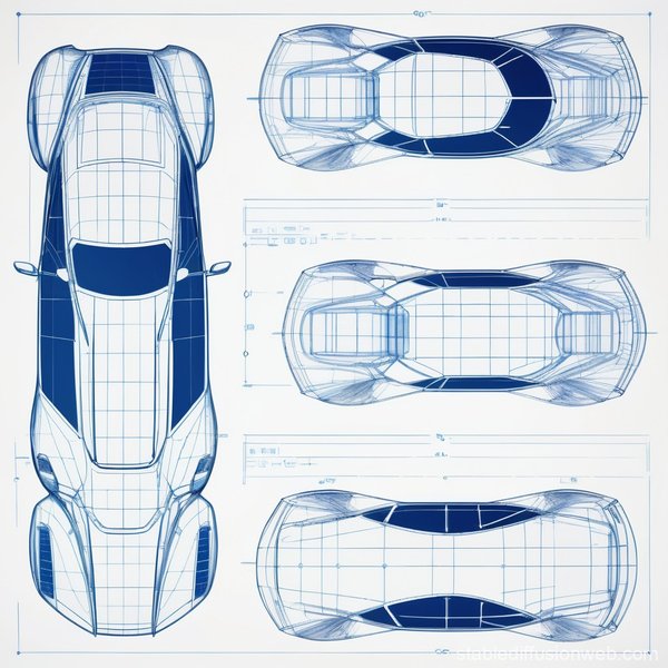
Conceptual rendering of a futuristic solar vehicle, emphasizing sleek lines and integrated solar panels.
Overall Layout and Key Component Integration
Structuring the Solar Vehicle for Optimal Performance
The vehicle layout is strategically designed to optimize weight distribution, aerodynamic profile, and component efficiency. It features an approximate length of 4.5 meters, a width of 1.8 meters, and a height of 1.2 meters, ensuring a low center of gravity and reduced frontal area.
Component Placement Strategy
- Solar Array: High-efficiency monocrystalline silicon photovoltaic panels are integrated flush onto the roof and potentially the hood, covering an estimated 4-6 square meters to maximize solar energy harvesting without disrupting airflow.
- Chassis and Body: A lightweight space frame or monocoque chassis constructed from aluminum alloys or carbon fiber composites provides structural rigidity while minimizing mass. The body panels are shaped for aerodynamic efficiency.
- Powertrain: A highly efficient brushless DC or permanent magnet DC electric motor is located near the rear axle, driving the rear wheels for optimal traction and packaging.
- Battery Storage: A modular lithium-ion battery pack is positioned low within the vehicle's underbody, contributing to a low center of gravity and improved handling dynamics.
- Cabin and Seating: The enclosed cabin features a tandem or staggered seating arrangement to maintain a narrow profile. It includes two fixed front seats and potentially up to three lightweight, foldable rear seats to accommodate 2 to 5 occupants flexibly.
- Wheels and Suspension: Four low-rolling-resistance tires are mounted on lightweight wheels. Aerodynamic fairings (wheel pants) enclose the wheels to minimize drag. An independent suspension system ensures ride comfort and stability.
- Thermal Management: Integrated cooling vents and potentially active cooling systems manage heat generated by the motor, battery, and electronics.
- Control Systems: An advanced power management system optimizes energy flow between the solar array, battery, and motor, incorporating regenerative braking to recapture energy during deceleration.
Visualizing the Design: Conceptual Sketches
Black and White Technical Representations
To visualize the layout and form, imagine simple black-and-white line drawings focusing on the vehicle's geometry and key component placement. These conceptual sketches adhere to the design principles outlined above.
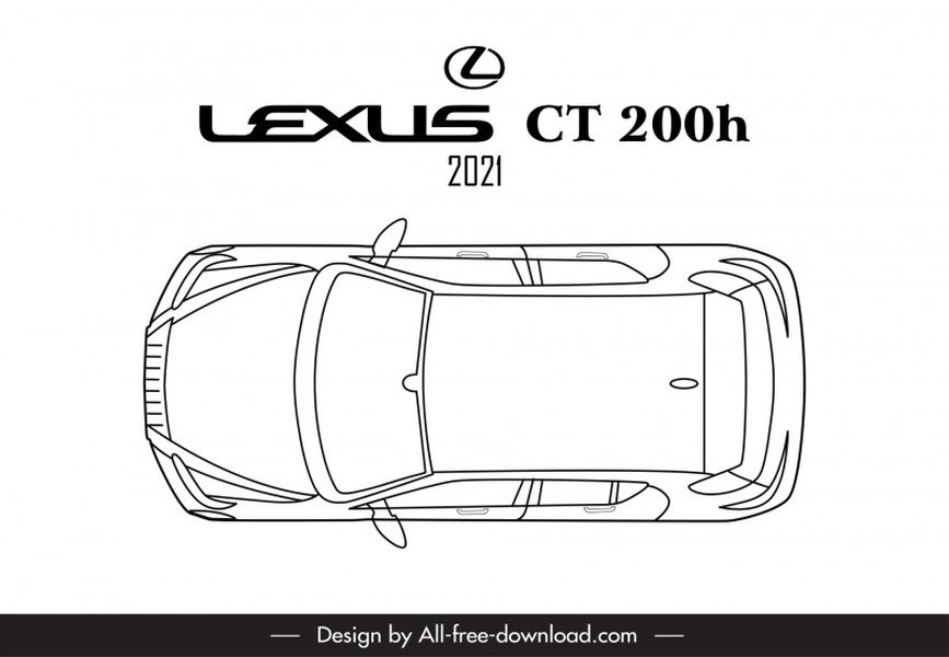
Illustrative example of a black and white top view sketch style, similar to how the solar car design would be represented.
Top View Sketch Description (Black & White)
The top view reveals an elongated, teardrop shape, approximately 4.5m long and 1.8m wide. The nose tapers significantly, while the tail is gently rounded. A large rectangular area dominates the upper surface, representing the flush-mounted solar panel array. Four circles depict the wheels, positioned at the corners and enclosed within streamlined fairings. Inside the central cabin area (indicated by dashed lines), two solid rectangles mark the fixed front seats, with three dotted rectangles behind them representing potential foldable rear seats. Arrows along the body contour indicate smooth airflow.
Side View Sketch Description (Black & White)
From the side, the vehicle presents a low, sleek profile, about 1.2m high. The silhouette follows a classic teardrop curve, sloping down towards the front and tapering gently upwards at the rear to manage airflow separation. The roofline is mostly flat to accommodate the solar array (shaded rectangle). The wheels are shown as circles within their aerodynamic fairings. The cabin enclosure is outlined, showing the position of the front seats and the space for optional rear seats. Dashed lines trace the intended smooth airflow path along the body. A small box near the rear axle indicates the motor/battery location.
Front View Sketch Description (Black & White)
The front view emphasizes the minimal frontal area, crucial for low drag. The shape is narrow (1.8m wide) and low (1.2m high), with aggressively rounded edges blending into the body sides. A narrow windshield slit follows the curved nose contour. The wheels are partially visible beneath their fairings on either side. A dark band across the upper section represents the continuation of the solar array onto the hood/front deck. Airflow lines would show the air splitting cleanly around the nose.
Aerodynamic Performance Insights: CFD Simulation
Visualizing Airflow and Pressure
Computational Fluid Dynamics (CFD) is essential for refining the external geometry to minimize aerodynamic drag. While a full simulation requires specialized software, we can describe the expected outcome based on the design principles and similar analyses found in research (like studies on the Merdeka 2 Solar Vehicle or general solar car aerodynamics).
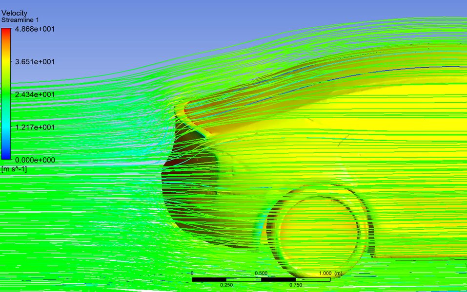
Example of CFD streamlines around a vehicle, illustrating how air flows over aerodynamic shapes.
CFD Simulation Result Description (Conceptual)
A simplified CFD simulation result visualization (imagine a black-and-white graphic) would depict the vehicle's side profile with overlaid airflow patterns (streamlines) and pressure zones. At a typical cruising speed (e.g., 60 km/h):
- Streamlines: Smooth, continuous lines flowing closely attached to the vehicle body from nose to tail, indicating laminar or minimally turbulent flow. Minimal flow separation would be visible at the rear taper, confirming the effectiveness of the teardrop shape.
- Pressure Contours: Shaded regions would show high pressure (darker grey) at the very front stagnation point, transitioning to lower pressure (lighter grey) along the curved top, sides, and gently tapering rear. The smooth pressure recovery at the back indicates low pressure drag.
- Key Metrics: Annotations would indicate a low predicted drag coefficient (Cd) in the target range of 0.12-0.15 and minimal aerodynamic lift, confirming the design's efficiency.
This simulation validates that the external geometry effectively minimizes air resistance, directly contributing to the vehicle's overall energy efficiency and range.
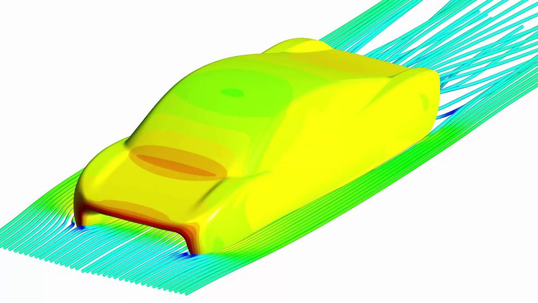
Example visualization from CFD post-processing, showing pressure or velocity contours used to analyze aerodynamic performance.
Design Parameter Focus
Balancing Key Performance Indicators
The design process involves balancing several critical parameters. The following chart illustrates the relative importance assigned to key design goals for this efficient solar commuter concept. Higher scores indicate greater emphasis during the conceptual design phase.
This radar chart highlights the primary focus on minimizing drag and weight, followed closely by optimizing the energy systems (solar panels, battery, powertrain). While seating flexibility is a requirement, it is balanced against the overriding goals of efficiency and performance within this conceptual framework.
Conceptual Framework Mindmap
Visualizing the Core Concepts and Components
This mindmap provides a visual overview of the solar vehicle's design philosophy, breaking down the core requirements, key components, and guiding principles.
(Carbon Fiber, Aluminum)"] id1_2_2["Structural Design"] id1_3["Low Aerodynamic Drag"] id1_3_1["Teardrop Shape"] id1_3_2["Smooth Surfaces"] id1_3_3["Wheel Fairings"] id1_3_4["Minimized Frontal Area"] id1_4["Seating Capacity"] id1_4_1["Minimum: 2 Seats"] id1_4_2["Maximum: 5 Seats"] id1_4_3["Modular/Flexible Layout"] id2["Key Components"] id2_1["Solar Array"] id2_1_1["High-Efficiency Panels
(Monocrystalline Silicon)"] id2_1_2["Surface Integration"] id2_2["Chassis & Body"] id2_2_1["Lightweight Frame"] id2_2_2["Aerodynamic Shell"] id2_3["Powertrain"] id2_3_1["Efficient Electric Motor
(Brushless DC / PMDC)"] id2_3_2["Drivetrain"] id2_4["Energy Storage"] id2_4_1["Lithium-Ion Battery"] id2_4_2["Battery Management System (BMS)"] id2_5["Wheels & Suspension"] id2_5_1["Low Resistance Tires"] id2_5_2["Aerodynamic Fairings"] id2_5_3["Independent Suspension"] id2_6["Control Systems"] id2_6_1["Power Management"] id2_6_2["Regenerative Braking"] id3["Design Process"] id3_1["Aerodynamic Analysis (CFD)"] id3_2["Structural Analysis (FEA)"] id3_3["Material Research"] id3_4["Component Integration"]
Key Specifications Summary
Target Parameters for the Solar Vehicle Concept
The following table summarizes the key target specifications for this conceptual solar vehicle design, based on the requirements and design philosophy.
| Parameter | Target Specification | Rationale |
|---|---|---|
| Seating Capacity | 2 (minimum) to 5 (maximum) | User requirement, flexible interior design. |
| Overall Length | ~ 4.5 meters | Balance between interior space and aerodynamic length. |
| Overall Width | ~ 1.8 meters | Minimize frontal area while allowing practical cabin width. |
| Overall Height | ~ 1.2 meters | Minimize frontal area and maintain low center of gravity. |
| Target Weight (Kerb) | < 300-400 kg (depending on configuration) | Critical for efficiency, achieved via lightweight materials. |
| Target Drag Coefficient (Cd) | 0.12 - 0.15 | Minimize aerodynamic losses for range extension. |
| Solar Panel Type | High-Efficiency Monocrystalline Silicon | Maximize power generation per unit area. |
| Solar Panel Area | 4 - 6 square meters | Maximize energy capture within vehicle footprint. |
| Solar Panel Efficiency | 20% - 25% | State-of-the-art conversion efficiency. |
| Battery Type | Lithium-Ion (High Energy Density) | Best balance of weight, capacity, and lifecycle. |
| Motor Type | Brushless DC / Permanent Magnet DC | High efficiency and reliability. |
Engineering and Design Insights
Exploring Solar Car Development
Building a successful solar car involves a complex interplay between engineering disciplines and innovative design thinking. The video below from Lightyear provides insights into the conceptualization, engineering, and design challenges faced when developing a solar electric vehicle intended for practical use, touching upon aspects relevant to our conceptual design.
This perspective highlights the journey from concept to a functional prototype, emphasizing the integration of solar technology, aerodynamics, and user-centric design – core elements considered in the vehicle concept presented here.
Frequently Asked Questions (FAQ)
Clarifying Key Aspects of the Design
What makes this design 'efficient'?
Efficiency stems from a multi-pronged approach:
- Low Aerodynamic Drag: The streamlined teardrop shape, smooth surfaces, and wheel fairings significantly reduce air resistance, minimizing the energy needed to move the car, especially at higher speeds.
- Lightweight Construction: Using materials like carbon fiber and aluminum reduces the vehicle's mass, requiring less energy for acceleration and climbing hills.
- High-Efficiency Components: Utilizing efficient solar panels, electric motors, and power electronics ensures that minimal energy is lost during conversion and use. Regenerative braking further recovers energy during deceleration.
How is the 2-to-5 seat flexibility achieved?
The design incorporates a modular interior. It features two standard fixed front seats. Behind these, space is allocated for up to three additional lightweight, foldable seats. When not needed, these rear seats can be folded down or potentially removed to save weight and increase cargo space, without fundamentally altering the vehicle's core structure or aerodynamic profile significantly. The narrow cabin might necessitate a staggered or tandem arrangement for rear passengers.
Can this car drive at night or on cloudy days?
Yes. The integrated lithium-ion battery pack stores energy generated by the solar panels during sunny periods. This stored energy powers the vehicle when sunlight is insufficient or unavailable, such as at night or during heavily overcast conditions. The vehicle's range under these conditions depends on the battery's state of charge and energy consumption.
What is the estimated range of this vehicle?
Estimating range precisely requires detailed simulation and depends heavily on battery size, driving conditions (speed, terrain, driving style), weather, and solar irradiance. However, based on the focus on high efficiency (low drag, low weight) and optimized solar capture, a practical daily range contributed by solar energy under good sunlight conditions could potentially be significant (e.g., adding dozens of kilometers). The total range on a full battery charge would depend on the pack size, but the combination aims for substantial self-sufficiency for typical commuting distances.
References
Sources Informing the Design Concept
- The Role of Aerodynamics in Solar Car Design - solarcarclub.com
- Solar Car Bodywork Construction - speedace.info
- 2015 Solar Car Conference Aerodynamics - americansolarchallenge.org
- CFD Analysis for Merdeka 2 Solar Vehicle - ResearchGate
- Aerodynamics of a Solar Car | Ansys Innovation Courses - ansys.com
- Aerodynamic analysis and improvements of a solar car - ResearchGate
Recommended Further Exploration
Delve Deeper into Solar Vehicle Technology
 scientificgems.wordpress.com
 michaelsri.wordpress.com

Last updated April 15, 2025