
Replacing the Knock Sensor on a 2008 Honda Odyssey
A step-by-step guide for DIY enthusiasts and professionals alike
Key Insights
- Proper Tooling and Preparation: Ensure necessary tools are at hand and follow safety protocols.
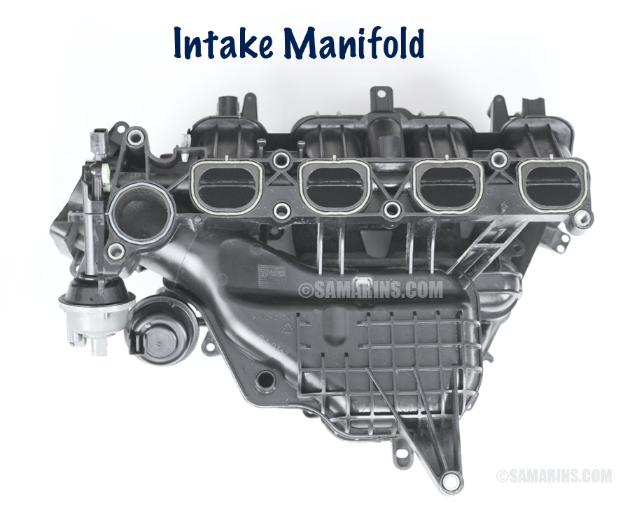
- Methodical Disassembly: Remove the intake manifold and related components for clear access to the sensor.
- Replacement and Reassembly: Install the new sensor with care including O-ring lubrication, and reassemble with torque specifications in mind.
Understanding the Knock Sensor
The knock sensor is an important component of your 2008 Honda Odyssey’s engine management system. Its primary function is to detect vibrations (engine knock) that occur when there is abnormal combustion in the engine cylinder. These vibrations can signify poor ignition timing or incorrect fuel-air mixtures, potentially damaging the engine over time if not addressed. By sending this information to the engine control module (ECM), the sensor works with the onboard computer to adjust the timing and maintain optimal engine performance.
Given that the sensor is typically positioned under the intake manifold, accessing and replacing it requires an understanding of the engine layout and a methodical disassembly process. The sensor is usually coupled with an O-ring to ensure a proper seal, and over time, this seal may degrade or the sensor wiring may suffer damage (often due to rodents), which in turn necessitates replacement.
Step-by-Step Replacement Process
Preparation and Safety
Before beginning, ensure your work environment is safe and organized. Always disconnect the negative battery terminal to prevent any accidental shorts or constraints from residual electrical energy. It is crucial to work with a cool engine to avoid any burn hazards. Gather all necessary tools and components including the new knock sensor with its replacement O-ring, deep socket set, extension bars, a torque wrench, and basic hand tools like pliers and screwdrivers.
Materials and Tools Required:
- New knock sensor (check for part number 30530-P8F-A01 or as specified in your vehicle manual)
- Deep socket set (including a 27mm socket for this model)
- Universal joint extension; consider also having a 2-inch extension for tight areas
- Pliers (needle-nose recommended)
- Long, slotted screwdriver (for depress release tabs on the connector)
- Engine oil (for O-ring lubrication)
- Torque wrench
- Clean rags and safety gloves/goggles
Disassembly: Gaining Access to the Sensor
Step 1: Disconnect the Battery
Start by disconnecting the negative terminal of your vehicle's battery. This precaution minimizes the risk of electrical shorts while you’re working in the engine compartment.
Step 2: Remove the Intake Manifold Cover and Components
The knock sensor is located beneath the intake manifold. To access it:
- First, remove the intake manifold cover. This may involve disconnecting attached vacuum lines, electrical connectors, and the air ducting system.
- Carefully detach the throttle body if required, ensuring that you note or mark the orientation of components.
- Remove any components that obscure access to the upper intake manifold, such as parts of the air intake or surrounding wiring.
Step 3: Removing the Upper Intake Manifold
The upper intake manifold must be removed to expose the sensor. Follow these steps:
- Locate and unbolt the manifold fasteners with the appropriate socket. It is important to carefully remove the manifold in the reverse order of its assembly to avoid damaging any gaskets or seals.
- As you lift off the manifold, be cautious of any residual grime; it can inadvertently fall into the cylinders.
- If the fuel rail assembly is obstructing your view or direct access, remove it with care; make sure to disconnect any fuel lines safely.
Sensor Removal and Inspection
Step 4: Locate and Disconnect the Knock Sensor
Once the intake manifold is out of the way, the sensor should be visible, typically positioned in the engine valley close to the engine block:
- Identify the knock sensor by its round shape and the associated electrical connector.
- Depress the release button on the wiring connector with the help of a long, slotted screwdriver.
- Gently pull the connector upward using needle-nose pliers, ensuring that you do not damage the wiring harness.
Step 5: Remove the Old Knock Sensor
Removing the sensor involves using a deep socket along with a universal joint and extension for proper alignment:
- Place the appropriate deep socket (27mm recommended) over the knock sensor.
- Using your ratchet and extension, carefully unthread and remove the sensor.
- As you remove it, pay attention to any signs of rodent damage or wear in the wiring harness, which may also need replacement or repair.
- Discard the old O-ring seal, as it cannot be reused reliably.
Installation of the New Knock Sensor
Step 6: Prepare the New Sensor
Before installation:
- Apply a small amount of clean engine oil to the new sensor’s O-ring. This helps ensure a proper seal and smooth installation.
- Make sure your new sensor matches your model specifications.
Step 7: Install the New Sensor
With the prepared sensor, begin installation:
- Carefully thread the new knock sensor into the mounting location that was vacated by the removed sensor.
- Using your deep socket and extension, secure the sensor by tightening it to the manufacturer’s recommended torque. This is typically in the range of \(15-20 \, \text{ft-lbs}\); be sure to check your specific vehicle’s service manual.
- Reconnect the electrical connector, ensuring that it clicks into place securely.
Step 8: Reassemble the Engine Components
With the sensor installed, it is time to reassemble the parts in reverse order of disassembly:
- Replace the fuel rail, intake manifold, and any air ducting components you previously removed. Take your time to ensure every gasket or seal is correctly placed, and consider replacing them if they show signs of wear.
- Reattach any disconnected wires, vacuum lines, and throttle components carefully.
- Double-check that all bolts and connectors are secured to the proper torque specifications.
Detailed Process Overview Table
| Step | Action | Key Points |
|---|---|---|
| 1 | Disconnect Battery | Ensure safety by disconnecting the negative terminal |
| 2 | Remove Intake Manifold Cover & Components | Disconnect vacuum lines, throttle body, and air ducting |
| 3 | Remove Upper Intake Manifold | Carefully unbolt manifold; avoid damaging gaskets |
| 4 | Disconnect Knock Sensor Wiring | Depress release button and remove connector without damage |
| 5 | Remove Old Sensor | Use proper socket & extension; check for rodent damage |
| 6 | Prepare New Sensor | Lubricate O-ring and verify correct part specification |
| 7 | Install New Sensor | Tighten to specification; reconnect wiring securely |
| 8 | Reassemble Components | Replace all removed parts in reverse order; check torques |
Practical Tips and Additional Considerations
Replacing the knock sensor on a 2008 Honda Odyssey requires attention to detail, particularly when working around the intake manifold and associated components. Here are some practical tips to ensure a smooth replacement:
Work Environment and Safety
Always ensure your vehicle is securely parked on a flat surface and the engine is completely cool before starting any work. Keeping your work area clean is essential to avoid the accidental introduction of dirt or debris into sensitive engine components. Wearing safety goggles and gloves protects you from potential hazards such as oil splashes or sharp edges on removed parts. Additionally, using a well-lit area or a headlamp will help in identifying small connectors and bolts during reassembly steps.
Inspecting the Wiring Harness
Before installing the new knock sensor, take extra time to inspect the sensor wiring harness for signs of wear, corrosion, or rodent damage. Rodents are known to chew on wiring, and any compromised wiring can lead to recurring issues even after sensor replacement. If any damage is detected, consider replacing the harness or obtaining a repair kit specifically designed to address the problem.
Torque Specifications and Sealing
Using a torque wrench during reassembly is crucial for ensuring that bolts are secured to the manufacturer’s specifications. Over-tightening can damage threads or the sensor itself, while under-tightening might lead to sensor movement and even engine misfires. Lubrication of the O-ring with a dab of engine oil before installation helps achieve a better seal, reducing the risk of leaks around the sensor mount. Make sure to tighten the sensor gradually and recheck the torque if necessary after reassembly.
Dealing with Unexpected Challenges
Occasionally, you may encounter difficulties such as restricted access due to stubborn connectors, corrosion around bolts, or the sensor threading being less visible once the manifold is removed. In these instances, a gentle but firm approach is recommended. If any part of the process feels too challenging, or if subsequent engine diagnostics indicate unresolved issues, consulting with a professional mechanic is advisable.
Testing and Final Checks
Once the installation is complete, performing thorough testing is essential before resuming regular vehicle operation. Reconnect the negative battery terminal and start the engine. Allow the engine to idle and listen for any unusual sounds. Watch for warning lights on the dashboard or any error codes that might be retrieved using an OBD-II scanner. It is particularly important to check around the intake manifold for any signs of leaks or loose connections.
Monitor the engine performance during a brief test drive to ensure that the engine control module (ECM) is accurately adjusting the timing based on sensor input without misfires or knocking noises. If any issues persist, re-inspect the wiring and ensure the sensor is correctly tightened and sealed.
Additional Practical Considerations
The replacement job, for those familiar with automotive repairs, generally takes between two to three hours. However, new DIYers might require additional time while consulting repair manuals or online guides to ensure every step is performed correctly. During reassembly, double-check every connector and vacuum line, as missing any can lead to additional engine performance issues post repair. Additionally, consider cleaning the work area and surrounding components before reassembly, as a clean engine bay can significantly reduce post-repair complications.
For budget estimates, expect parts and labor to range in total between roughly $310 and $379, if opting by labor rates. While the sensor itself is relatively inexpensive (around $40), the real cost can come from the labor-intensive nature of this job. Being aware of these costs can help you decide if this is a repair you want to approach yourself or have handled by a professional.
References
- OEM Honda Odyssey Knock Sensor - HondaPartsNow
-
Knock Sensor Replacement Guide - OdyClub Forum
- Knock Sensor Replacement Cost - RepairPal
- AutoZone: 2008 Honda Odyssey Knock Sensor
- Replacement Knock Sensor on Amazon
- Knock Sensor Location Help - 2CarPros
- AutoZone Homepage
- Official Honda Website
-
OdyClub Forums
- RepairPal Homepage
Recommended Related Queries

Last updated March 2, 2025